



Thermal barrier coatings protect gas turbine hardware by reducing heat flow into cooled metal components. Their reliability depends on the complete coating system and operating environment.
For technical evaluators, ceramic temperature capability alone is an inadequate selection criterion. Bond-coat oxidation, thermal cycling, cooling performance, and deposit chemistry often determine service life.
This article explains how these multilayer systems work, why they fail, and which evidence helps distinguish credible coating performance from impressive but incomplete specifications.
How Does a Thermal Barrier Coating Protect Turbine Hardware?
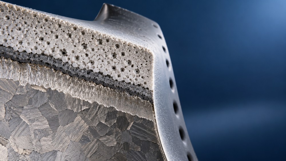
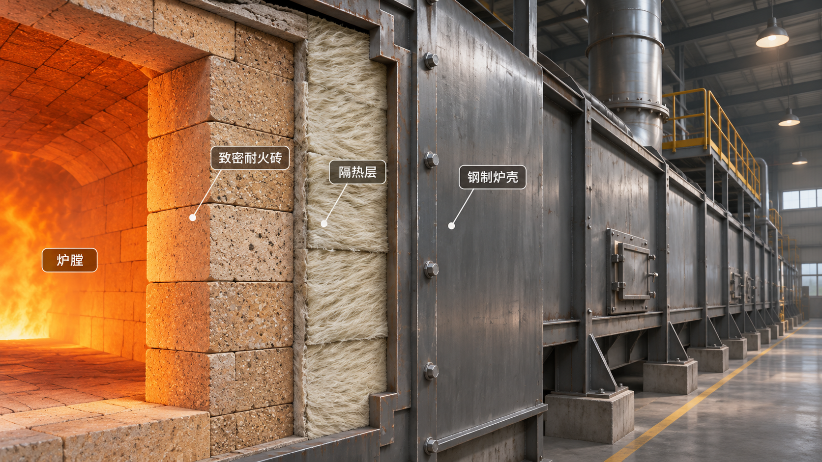
A typical thermal barrier coating system combines a nickel-based superalloy substrate, an oxidation-resistant metallic bond coat, a thermally grown oxide, and a ceramic topcoat.
The ceramic provides thermal resistance. The bond coat supports adhesion and supplies aluminum that forms a protective oxide, ideally a slow-growing, continuous alumina layer.
The substrate carries mechanical loads, while internal cooling and sometimes external film cooling remove heat. The coating works alongside these features throughout turbine operation.
Across a simplified coating layer, the temperature difference follows ΔT ≈ q″t/k, where q″ represents heat flux, t represents thickness, and k represents thermal conductivity.
This relationship explains why thicker coatings and lower conductivity can improve insulation. Actual component temperatures also depend on convection, radiation, cooling geometry, and local flow.
A quoted temperature reduction therefore needs boundary conditions. Evaluators should establish whether testing held gas temperature, heat flux, coolant flow, or substrate temperature constant.
Thermal barrier coatings can support higher firing temperatures, lower cooling demand, or improved component durability. Available benefits depend on how designers allocate the thermal margin.
In industrial thermal management, this distinction matters: a coating cannot independently establish an efficiency gain without considering the turbine cycle, cooling requirements, and maintenance consequences.
Which Material and Deposition Choices Matter Most?
Conventional topcoats commonly use zirconia stabilized with approximately seven to eight weight percent yttria, usually called YSZ. Its performance reflects a useful balance of properties.
YSZ combines relatively low thermal conductivity, useful toughness, and thermal expansion reasonably compatible with metallic substrates. Its porous or columnar architecture accommodates differential thermal strain.
Air plasma spraying, or APS, typically produces lamellar coatings containing splat boundaries, pores, and cracks. These features influence conductivity, compliance, adhesion, and degradation during service.
Electron beam physical vapor deposition, or EB-PVD, typically creates columnar structures with good strain tolerance. It is frequently selected for demanding rotating airfoil applications.
Neither method guarantees superior lifetime across all duties. Surface preparation, coating geometry, processing consistency, erosion exposure, and the required thermal resistance affect the comparison.
Bond-coat options include diffusion aluminides, platinum-modified aluminides, and MCrAlY overlays, where M denotes nickel, cobalt, or both. Selection must account for substrate compatibility and exposure.
Advanced ceramics, including rare-earth zirconates, can offer lower conductivity or improved resistance to particular degradation mechanisms. They may introduce compromises in toughness, expansion, or compatibility.
Multilayer designs can combine complementary materials, but every additional interface requires justification. Request evidence that the architecture retains adhesion and thermal performance after representative aging.
Why Does Oxidation Eventually Cause Coating Separation?
Oxygen can reach the bond coat through the ceramic, allowing a thermally grown oxide, or TGO, to develop. Controlled alumina formation initially provides essential protection.
As the oxide thickens, growth strains and thermal expansion differences create stresses. Cooling from operating temperature can intensify the forces driving interfacial crack formation.
Local interface roughness and bond-coat deformation can concentrate those stresses. Repeated exposure may produce rumpling, progressive cracking, and eventual separation of the ceramic layer.
Aluminum depletion also changes the system over time. Oxidation and interdiffusion with the substrate can reduce the bond coat’s ability to maintain protective alumina.
Less protective mixed oxides may then develop in susceptible regions. Contamination and manufacturing defects can further weaken interfaces, accelerating damage under otherwise comparable thermal exposure.
There is no universal critical TGO thickness that predicts failure across all coatings. Chemistry, interface geometry, residual stress, temperature history, and cycling conditions influence the outcome.
Evaluators should request cross-sectional microscopy showing oxide continuity, thickness distribution, crack location, and bond-coat condition. Average oxide thickness alone can conceal severe local damage.
A useful failure investigation identifies where separation occurred: within the ceramic, inside the oxide, or along an interface. Each location points toward different corrective actions.
How Do Thermal Cycling and Sintering Shorten Service Life?
Gas turbine components expand during heating and contract during cooling. Differences among ceramic, oxide, bond coat, and substrate generate stresses throughout each operating cycle.
Frequent starts, rapid shutdowns, and steep temperature gradients can promote cracking even when peak temperatures remain acceptable. Operating history therefore matters alongside maximum temperature.
Long exposure at elevated temperature also causes ceramic sintering. Pores and fine cracks can close, changing the features that originally provided insulation and compliance.
Sintering commonly increases thermal conductivity and stiffness. The coating may transmit more heat while becoming less able to accommodate thermal strain during subsequent cycling.
Conventional YSZ additionally faces phase-stability limitations under sufficiently severe temperature and time combinations. Practical limits depend on composition, microstructure, exposure duration, and the complete architecture.
A continuous-duty turbine and a frequently cycled peaking unit can therefore challenge the same coating differently. Neither operating hours nor cycle count provides sufficient context alone.
Laboratory furnace cycling helps compare oxidation and cyclic durability, but it does not reproduce every service stress. Burner rigs can introduce more representative thermal gradients.
Ask how specimens were heated, cooled, and supported, and how failure was defined. Rankings can change when test conditions better match component duty.
What Makes Erosion, Deposits, and Cooling Problems Dangerous?
Particle erosion progressively removes ceramic material and changes surface roughness. Impact velocity, angle, particle properties, and coating microstructure determine how quickly protective thickness is lost.
Foreign object impacts can create localized cracks or delamination that later expand during thermal cycling. Visible impact damage should trigger examination of surrounding coating integrity.
Ingested dust and ash can produce calcium-magnesium-alumino-silicate deposits, commonly called CMAS. Their melting behavior varies with chemistry, so exposure cannot be characterized by temperature alone.
When molten deposits wet and infiltrate an accessible coating microstructure, they can reduce strain tolerance. Chemical reactions may also destabilize the ceramic or alter protective features.
During cooling, infiltrated material can stiffen affected regions and promote cracking. Damage depends on deposit composition, loading, exposure time, temperature gradients, and coating architecture.
CMAS attack should be distinguished from hot corrosion involving aggressive salts and other contaminants. The mechanisms overlap operationally but require different evidence and mitigation choices.
Cooling deterioration adds another failure route. Blocked passages, restricted film-cooling holes, or altered flow distribution can raise metal temperatures despite apparently intact ceramic coverage.
For turbines exposed to dusty air or variable fuels, evaluation should connect filtration, fuel quality, deposit analysis, and cooling inspection with the coating damage map.
Which Performance Evidence Should Technical Evaluators Request?
Begin with the intended duty: component location, substrate alloy, gas conditions, expected metal temperature, cooling arrangement, operating hours, starts, and likely contaminants or deposits.
Then request the complete coating specification, including bond-coat chemistry, deposition method, thickness ranges, surface preparation, heat treatment, and acceptance criteria for defects and geometry.
Thermal conductivity data should identify measurement temperature and material condition. Values from pristine specimens may poorly represent coatings after sintering, oxidation, or deposit exposure.
Durability comparisons need consistent substrates, bond coats, specimen geometry, and failure criteria. A longer laboratory lifetime means little when test temperatures or cooling schedules differ.
Ask for specimen counts and scatter, not only the best result. Manufacturing variability can determine whether a promising coating delivers predictable performance across production batches.
Service references carry greater weight when component location, duty cycle, environment, and inspection findings resemble the proposed application. Similar turbine ratings alone establish limited comparability.
Separate measured findings from modeled benefits. A predicted reduction in substrate temperature requires validated boundary conditions before supporting claims about component life or cooling savings.
Finally, assess repairability: stripping limits, substrate damage, permissible repair cycles, cooling-hole restoration, and inspection access. These constraints can materially change the value of longer coating life.
How Can a Failure Investigation Lead to Better Decisions?
Start by mapping damage against component geometry and operating history. Leading edges, cooling-hole regions, platforms, and deposit-rich surfaces may reveal distinct local exposure conditions.
Record startup events, overtemperature excursions, fuel changes, and cooling abnormalities. These records help determine whether degradation accumulated gradually or followed a specific operational upset.
Preserve representative damaged and apparently sound areas for comparison. Cleaning or aggressive preparation can remove deposits and fragile interfaces needed to identify the initiating mechanism.
Use cross-sectional microscopy and appropriate chemical analysis to examine oxide growth, infiltration, cracking, and bond-coat depletion. Surface appearance alone rarely establishes the root cause.
Combine those findings with thickness measurements, cooling inspections, and temperature evidence. Spallation may be the final visible event after several interacting mechanisms weakened the system.
For example, deposit infiltration may reduce ceramic compliance while oxide growth increases interfacial stress. Subsequent cycling can then detach material that survived earlier operating periods.
Corrective action should follow the evidence: modify coating architecture, improve deposition control, reduce contaminant exposure, restore cooling, or adjust operating practices where technically justified.
Inspection intervals should reflect demonstrated damage progression and component criticality. A single generic coating lifetime cannot reliably support maintenance planning across different machines and duties.
Choosing a Coating Means Choosing a Validated System
Thermal barrier coatings deliver value when insulation, oxidation resistance, strain tolerance, and cooling performance remain balanced throughout the intended operating duty and maintenance interval.
The strongest selection case connects representative test results with reproducible manufacturing, inspectable degradation, and practical repair limits. Initial conductivity or maximum temperature capability cannot establish reliability alone.
For technical evaluators, the decisive question is whether the complete coating system has demonstrated acceptable degradation under comparable conditions, with evidence supporting both performance and maintenance expectations.