
How Thermal Barrier Technology for Kilns Reduces Heat Loss




When a kiln shell runs hotter than expected, heat is escaping through the lining as well as from openings, seals, and exposed metalwork. Thermal barrier technology for kilns reduces the conductive heat flow through the wall by placing lower-conductivity materials between the hot process and the steel shell. The resulting lower shell temperature also reduces heat lost from the outside surface by radiation and convection.
A cooler shell alone, however, does not establish whether a lining change is successful. The barrier must withstand the temperature, atmosphere, mechanical loading, and thermal cycling at its installed position. It must also preserve the hot-face conditions needed for the process. A useful assessment therefore connects a heat-loss calculation with a review of lining durability and operating constraints.
The heat path through a kiln wall
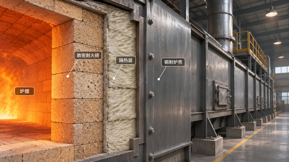
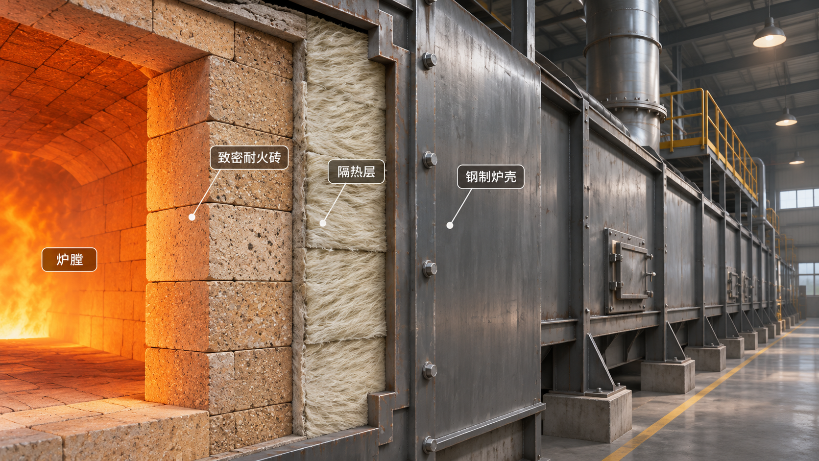
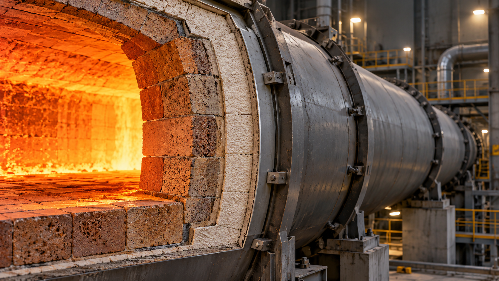
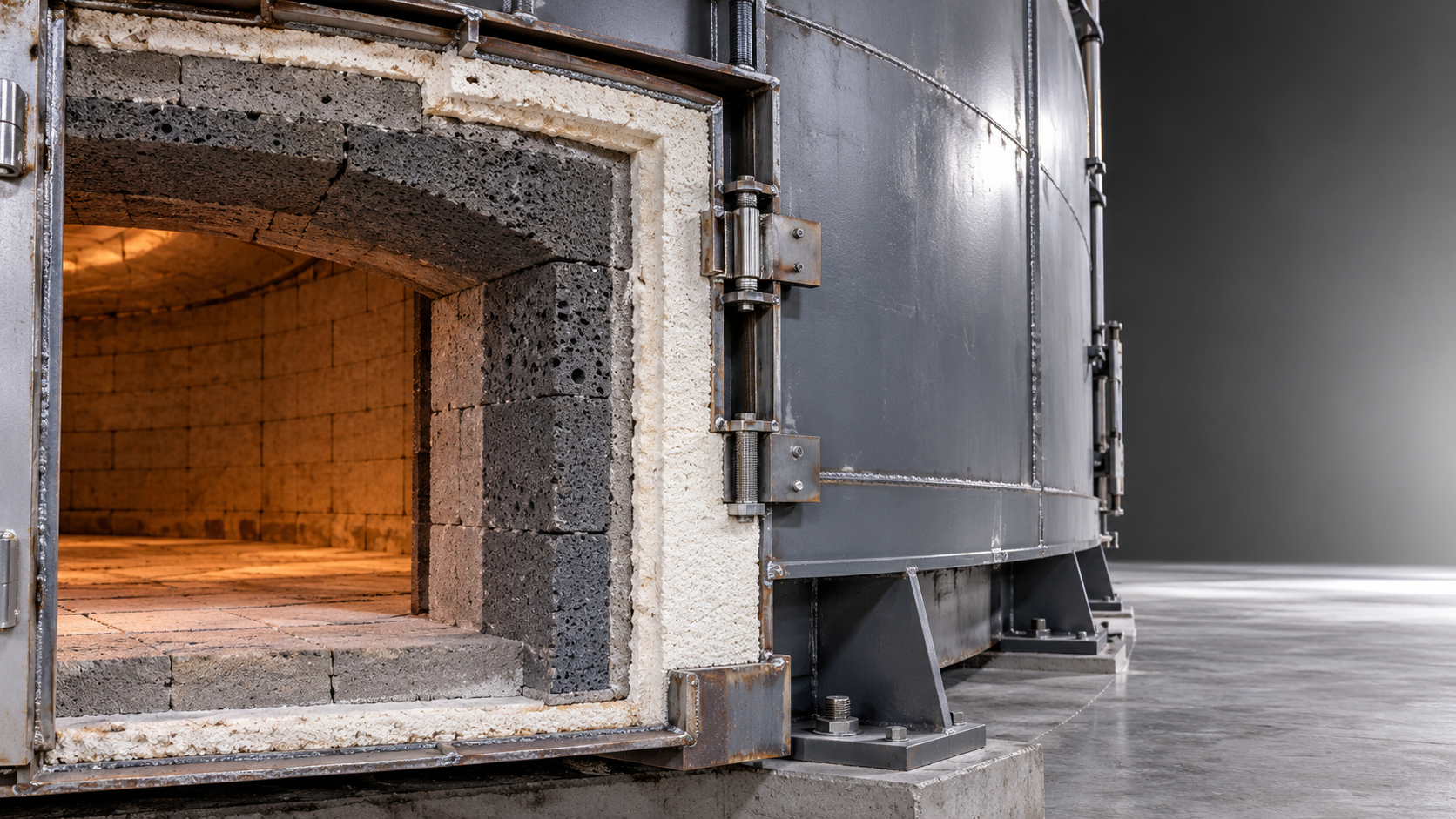
Heat moves from the kiln interior to the hot face by radiation and convection, then through the lining primarily by conduction. In a multilayer wall, each layer adds thermal resistance. Dense working refractory typically protects against abrasion, chemical attack, and mechanical stresses, while an insulating backup layer reduces the heat reaching the shell. Some kiln designs use insulating refractory as part of the working lining where the process environment permits it.
For a simplified flat wall at steady state, conductive heat flux can be estimated as q = (Thot face − Tshell inner face) / Σ(L/k), where L is layer thickness and k is thermal conductivity at the relevant temperature. All layers must use consistent units. The temperature difference in this expression is across the lining itself, not automatically between the kiln gas and ambient air. Gas-side and external surface heat-transfer resistances require separate treatment.
This relationship explains why increasing insulation thickness or reducing conductivity can lower heat flow. It is not a complete kiln model: conductivity changes with temperature, contact between layers may be imperfect, and real walls contain joints and penetrations. For a rotary kiln, radial conduction through cylindrical layers is more appropriate than a flat-wall approximation, particularly where lining thickness is not small relative to shell radius.
Separate wall losses from other escape routes
Before comparing lining materials, establish where energy is leaving the system. A hot shell may indicate a worn lining, a thermal bridge, a different internal temperature profile, or simply a high-temperature zone operating as designed. Likewise, low shell temperature does not rule out substantial losses elsewhere.
- Wall and roof surfaces: Distributed heat loss depends on surface temperature, exposed area, air movement, and surrounding temperatures. Local hot spots deserve separate investigation rather than being averaged across the whole shell.
- Doors, seals, and openings: Radiation through an opening and leakage of hot gases can be significant. Adding insulation to an adjacent wall will not necessarily address a poorly sealed opening.
- Metal attachments and supports: Anchors, frames, and structural penetrations can conduct heat through an otherwise effective insulating layer. Their temperature limits and connection details matter as much as their contribution to total loss.
- Process and exhaust streams: Hot product, exhaust gas, cooling air, and moisture carry energy away. These are not all shell losses, and a lining upgrade cannot be credited with eliminating them.
Map shell temperatures together with kiln operating zone, throughput, fuel input, and relevant process temperatures. A fixed kiln can be surveyed by surface area; a rotating shell requires measurements that account for rotation and changing viewing angles. Compare readings under reasonably stable conditions, because start-up, shutdown, and changing loads can temporarily distort the apparent heat-loss pattern.
Choosing a barrier without compromising the working lining
The lowest quoted thermal conductivity is not automatically the best selection. The hot-face material and backup insulation have different responsibilities, and the interface temperature between them determines whether the proposed combination is viable. A more insulating layer can raise the temperature of material on its hot side, even while it cools the shell.
Dense refractory and insulating refractory
Dense refractory brick or castable is often selected where contact with charge material, abrasion, slag, dust, or mechanical loading makes a robust working surface necessary. Its thermal conductivity can be higher than that of lightweight insulation, so a dense lining alone may allow substantial heat flow. Adding a compatible backup layer can reduce that flow, provided there is space and the resulting temperature profile remains acceptable.
Insulating firebrick and lightweight insulating castables provide lower conductivity through controlled porosity. They may serve as backup insulation or, in less aggressive conditions, as part of the hot-face lining. Their lower density does not make them interchangeable with dense materials: abrasion resistance, strength, chemical compatibility, and limits under sustained load must be checked against the actual duty.
Fibrous and microporous insulation
High-temperature insulating fibres can provide low thermal mass and rapid thermal response in suitable static assemblies. Their use depends on hot-face temperature, gas velocity, atmosphere, contamination, anchorage, and applicable handling controls. Fibre classification and occupational exposure requirements vary by material and jurisdiction; the material documentation and local requirements should govern handling and selection.
Microporous boards or panels can deliver high thermal resistance in a limited thickness, making them useful behind a protective lining where space is constrained. They still have specified temperature, compression, moisture, and installation limits. A design that places such a layer behind dense refractory must verify the calculated interface temperature and ensure the panel is protected from conditions for which it was not designed.
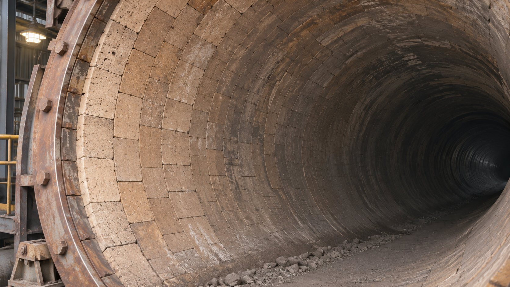
In rotary kilns, the lining must also tolerate shell ovality, movement, and operating loads. An insulating layer that works in a static furnace wall is not automatically suitable behind rotary kiln brick. Review retention, compressibility, brick stability, and shell-temperature effects as a complete lining system rather than selecting backup insulation in isolation.
Read material data at the temperatures that matter
A conductivity value supplied at one mean temperature should not be used unchanged across a steep temperature gradient without justification. Request conductivity data over the expected operating range and use a temperature-dependent calculation when the difference is material to the decision. For layered walls, solve for interface temperatures as well as shell temperature; the answer for one layer depends on the resistance of all the others.
Service temperature is another frequent source of confusion. A stated classification or maximum temperature is not necessarily an unlimited continuous hot-face rating under load, chemical attack, or cycling. Ask what the limit represents, how it was determined, and whether shrinkage, strength, or dimensional stability data apply to the intended exposure. Compare test conditions and specimen condition before ranking materials from different suppliers.
Other properties can govern service life even when a thermal model looks favorable:
- Permanent linear change: Excessive shrinkage can open joints or loosen a lining; expansion can generate damaging restraint forces.
- Thermal shock resistance: Rapid heating, cooling, or local temperature swings can cause cracking or spalling.
- Chemical resistance: Alkalis, sulfur compounds, vapors, slags, and infiltrating dust can alter refractory properties or attack particular compositions.
- Mechanical behavior: Strength, abrasion resistance, creep, and compression limits must match the position and load, including stresses during operation and shutdown.
Material standards can make comparisons more consistent, but the designation alone is not proof of fitness for a kiln. Confirm the exact standard and edition referenced in a supplier’s test report, the property measured, and the test temperature. Where a project specification names a standard, verify that it applies to the material form and property being compared rather than assuming that one classification covers the entire lining assembly.
Estimate the potential saving, then test the assumptions
A practical comparison starts with a baseline heat-loss model and a proposed lining model using the same operating conditions. Divide the kiln into zones where process temperature, lining construction, shell diameter, or exposure differs substantially. Calculate the heat loss for each zone and multiply by its exposed area. For cylindrical sections, use the relevant inner and outer radii; do not apply a single flat-wall area indiscriminately across all layers.
External losses require surface convection and radiation. The radiation estimate depends on shell emissivity and surrounding surface temperatures; convection depends partly on air movement and surface orientation. An infrared camera measures apparent temperature based on settings and viewing conditions, so emissivity, reflected radiation, distance, and surface condition must be checked. A shiny or oxidized patch can produce a misleading comparison even when adjacent metal is at a similar actual temperature.
The difference between modeled baseline and proposed shell loss is an estimate of reduced heat leaving through the evaluated surfaces. It is not automatically an equal reduction in purchased fuel. Burner efficiency, combustion control, heat recovery, production rate, and changes in process temperature affect the fuel response. For intermittent kilns, include the energy stored in the lining and the heating and cooling cycle; a steady-state calculation alone can miss a material part of the duty.
- Record the existing lining thicknesses, material condition, shell dimensions, operating schedule, and zone temperatures. Identify missing or uncertain inputs.
- Calculate baseline surface loss and compare predicted shell temperatures with representative measurements. Investigate large discrepancies before using the model to rank alternatives.
- Model each proposed layer with its expected temperature-dependent properties and calculate interface temperatures, shell temperature, and heat flow.
- Check mechanical, chemical, and installation constraints, including allowances for joints, anchors, movement, and manufacturing tolerances.
- Convert the heat-loss difference to an operating-period estimate using representative hours and explicitly stated efficiency assumptions. Show a range where inputs are uncertain.
A sensitivity calculation is especially useful when shell emissivity, conductivity at service temperature, or operating hours are poorly known. Change one assumption at a time to see whether the preferred option remains the same. If a small change reverses the ranking, obtain better data before treating the estimate as a design basis.
Installation details that can erase the modeled advantage
Gaps, compressed insulation, misplaced joints, and discontinuities around anchors can create local heat paths that are absent from an ideal layer calculation. Installation drawings should show layer order, joint treatment, support details, and how insulation is protected at openings and transitions. Follow the material supplier’s requirements for storage, cutting, dry-out, and heating rates; trapped moisture or an unsuitable heat-up schedule can damage some refractory systems.
After installation, compare a new thermal survey with the baseline at comparable throughput and operating temperatures. Look for persistent local hot spots, not just a lower average. A developing hot spot may indicate displaced insulation, joint opening, refractory loss, or a change in internal conditions; it is a diagnostic signal, not proof of a single failure mechanism.
Any proposed change that raises the hot-face or interface temperature, alters rotary kiln lining support, or affects shell integrity should be reviewed against the kiln’s mechanical and process design before implementation. The strongest thermal barrier is the one that maintains its intended resistance throughout the operating cycle without transferring the risk to the working lining or shell.
Related News
 Ms. Elena RodriguezProcess Equipment Pricing: How to Compare Quotes and Total CostsMaster process equipment comparison pricing: compare supplier quotes, uncover hidden costs, and evaluate lifetime expenses to make a confident buying decision.Nov 17, 2026
 Prof. Marcus ChenGlobal Cement Industry Decarbonization: Key Technologies and Cost BarriersExplore global cement industry decarbonization technologies, cost barriers, and practical investment strategies to cut emissions while protecting competitiveness.Nov 16, 2026
 Structural Material AnalystChoosing Specification Preparation Support for North American ProjectsChoose specification preparation support North America projects can rely on. Compare technical expertise, compliance, interfaces, and supplier acceptance criteria.Nov 14, 2026
 Structural Material AnalystSpecialty Ceramic Extrusion: How Material Properties Affect FormingExplore how ceramic specialized material extrusion is shaped by particle size, binders, and solids loading—and learn to improve forming and reduce defects.Nov 13, 2026
 Ms. Elena RodriguezHigh-Pressure Molding Equipment Prices in Europe: What Affects the Total Cost?Explore high pressure molding equipment price Europe buyers can expect to assess, from tooling and installation to running costs. Compare quotes with confidence.Nov 12, 2026
 Structural Material AnalystChoosing a Vacuum Extrusion System: Capacity, Materials and Vacuum LevelsChoosing a vacuum extrusion system? Compare capacity, material behavior and vacuum levels to improve product quality and select the right equipment.Nov 11, 2026
 Optical Glass Tech FellowGlass Melting Innovations: Comparing Electric and Hybrid Furnace TechnologiesExplore glass melting innovations and compare electric and hybrid furnaces by energy use, emissions, glass quality and operating costs to find the right fit.Nov 10, 2026
 Thermal Energy ArchitectHow Thermal Barrier Technology for Kilns Reduces Heat LossDiscover how thermal barrier technology for kilns reduces heat loss, and learn how to select insulation and assess savings without compromising lining durability.Nov 09, 2026
 Prof. Marcus ChenGlobal Materials Trends: What North American Manufacturers Need to KnowExplore global material trends North America manufacturers need to know, from energy costs and supply chains to lower-carbon materials and smarter investment decisions.Nov 08, 2026
 Thermal Energy ArchitectSelecting Abrasion-Resistant Refractories for High-Wear Kiln LiningsExplore advanced refractory materials abrasion resistant enough for high-wear kiln linings. Compare wear mechanisms, thermal stability, installation and lifecycle costs.Nov 06, 2026
 Dr. Alistair VaughnIndustrial Energy Efficiency Certification: ISO 50001 Requirements for PlantsExplore industrial energy efficiency certification with ISO 50001. Learn how plants define scope, measure performance and prepare credible evidence for audits.Nov 05, 2026
 Ms. Elena RodriguezWhat Is an Industrial Intelligence Database and How Is It Used?Discover how an industrial intelligence database helps researchers map markets, track projects, compare technologies, and assess evidence with confidence.Nov 04, 2026
 Ms. Elena RodriguezIndustrial Material Pricing: How Freight and Order Volume Affect QuotesExplore industrial material pricing and learn how freight, order volume, and inventory costs affect quotes. Compare suppliers and make smarter purchasing decisions.Nov 03, 2026
 Structural Material AnalystSingle- vs. Twin-Screw Extrusion Systems: Which Suits Your Material?Choose the right specialized extrusion systems screw type for your material. Compare single- and twin-screw options to improve quality and control costs.Nov 02, 2026
 Thermal Energy ArchitectChoosing Thermal Barrier Materials for Kilns: Temperature and Heat LossExplore thermal barrier materials for kilns and learn how to balance temperature resistance, heat loss, durability and operating costs when selecting a lining.Nov 01, 2026
 Ms. Elena RodriguezSupplier Reference Platform Pricing: Fees and Contract Terms to CompareCompare supplier reference platform pricing, hidden fees, verification costs and contract terms to choose the right solution for your sourcing team.Oct 31, 2026
 Ms. Elena RodriguezSupplier Comparison Metrics: How to Score Cost, Quality, and DeliveryUse supplier comparison metrics to score cost, quality, and delivery with a practical weighted scorecard. Make more confident equipment sourcing decisions.Oct 30, 2026
 Ms. Elena RodriguezWhat Does Industrial Waste Heat Recovery Cost, and When Does It Pay Back?Understand industrial waste heat recovery cost, from equipment and installation to net savings. Learn how to compare quotes, assess risks, and calculate realistic payback before investing.Oct 29, 2026
 Thermal Energy ArchitectChoosing Industrial Waste-to-Energy Equipment by Waste Moisture and Heating ValueChoose industrial waste to energy equipment by moisture and heating value. Compare technologies, fuel needs, and supplier guarantees to make a confident investment.Oct 28, 2026
 Thermal Energy ArchitectChoosing Industrial Kiln Insulation for High Heat and Repeated Thermal CyclingExplore high temperature industry solutions for kiln insulation under repeated thermal cycling. Compare materials, reduce heat loss, and select the right lining for your operating conditions.Oct 27, 2026

Related News
- 00
0000-00
How Thermal Barrier Technology for Kilns Reduces Heat Loss - 00
0000-00
Selecting Abrasion-Resistant Refractories for High-Wear Kiln Linings - 00
0000-00
Choosing Thermal Barrier Materials for Kilns: Temperature and Heat Loss - 00
0000-00
Choosing Industrial Waste-to-Energy Equipment by Waste Moisture and Heating Value - 00
0000-00
Choosing Industrial Kiln Insulation for High Heat and Repeated Thermal Cycling
0000-00
Weekly Insights
Stay ahead with our curated technology reports delivered every Monday.