
Choosing Industrial Kiln Insulation for High Heat and Repeated Thermal Cycling




Industrial kiln insulation should be selected for its ability to stay effective through the full operating cycle. A material that tolerates the peak temperature may still shrink, open joints, or lose strength after repeated heating and cooling. For teams comparing high temperature industry solutions, the strongest starting point is a lining design that matches the kiln’s temperature profile, atmosphere, mechanical loads, and shutdown pattern.
Frequently cycled, clean furnaces often benefit from lightweight insulation because less energy goes into heating the lining. Kilns exposed to abrasion, moving material, corrosive deposits, or flame impingement may need a more durable working face over insulating backup layers. The choice depends on where each material sits and what reaches it during operation.
Define the operating conditions before comparing materials
A maximum operating temperature is only one part of the specification. Two kilns reaching the same peak temperature can require different linings if one operates continuously and the other cools between batches. Rapid temperature changes create uneven expansion through the lining, while long holds can encourage permanent shrinkage or chemical attack.
Build the selection around these operating details:
- Temperature profile: Normal operating temperature, peak excursions, holding time, and local hot spots near burners or process reactions.
- Thermal cycling: Heating and cooling rates, shutdown frequency, cooling method, and door-opening events.
- Atmosphere: Oxidizing or reducing conditions, water vapor, combustion products, and process gases.
- Material exposure: Dust, alkalis, salts, molten phases, slag, and abrasive feed.
- Mechanical conditions: Vibration, rotation, impact, gas velocity, and loads carried by the lining.
- Design constraints: Available thickness, shell-temperature limits, support geometry, and maintenance access.
Use conditions at the lining surface wherever possible. A chamber thermocouple may miss a burner hot spot, and an average gas analysis may conceal aggressive deposits in cooler zones. In rotary equipment, rotation and movement of the charge also limit where lightweight insulation can be used safely.
Compare materials by their role in the lining
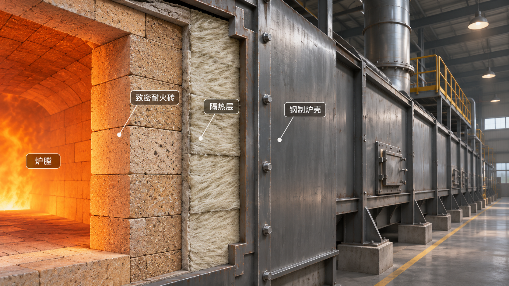
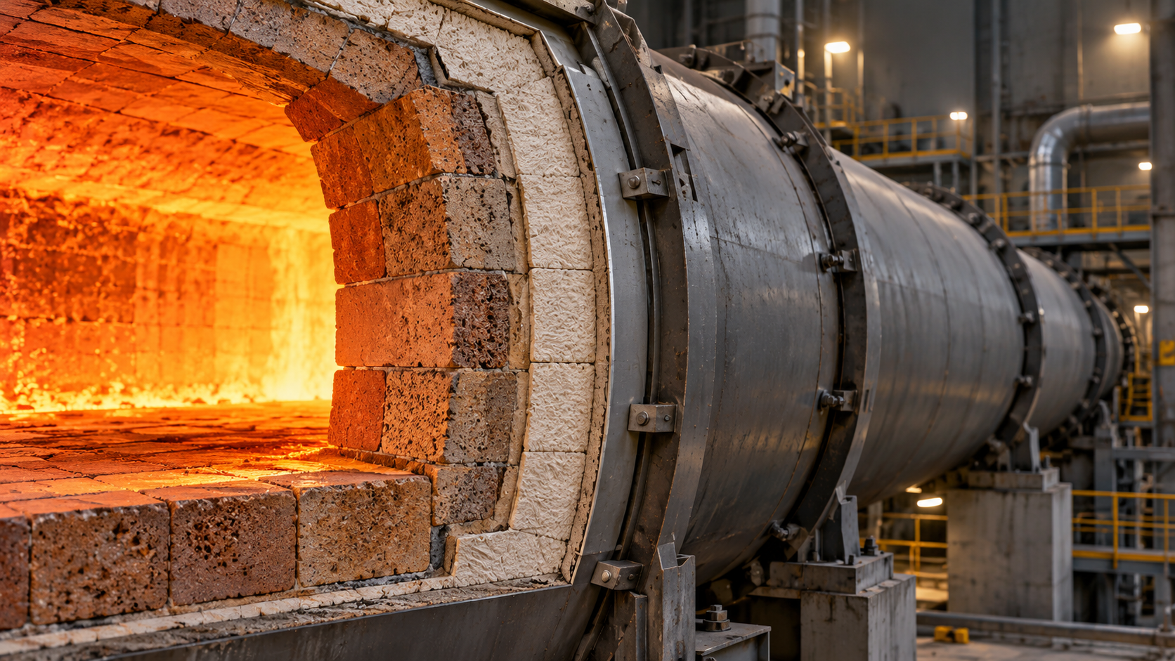
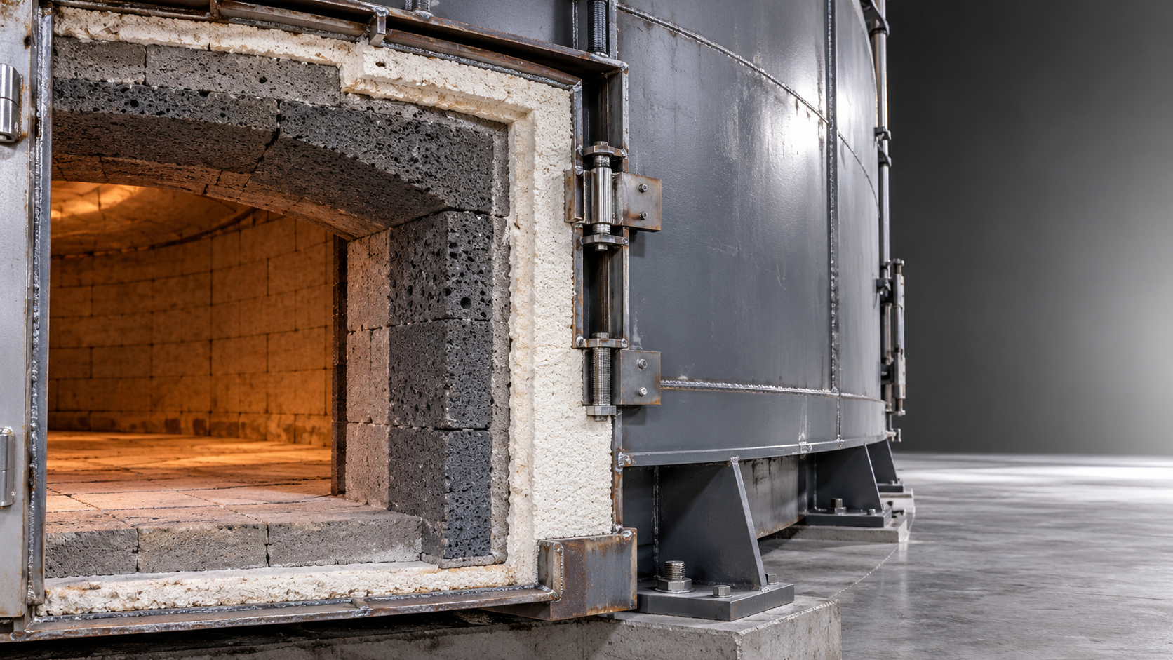
The practical choice is often a layered system. The working face handles direct process exposure; the backup insulation limits heat flow toward the shell. Asking one material to provide chemical resistance, abrasion resistance, structural strength, and low thermal conductivity can lead to compromises.
These categories are broad. Refractory fibers differ in composition and service capability, while insulating bricks and castables vary substantially in strength and conductivity. Compare specific grades against the duty. A claim that one material family is universally superior offers little help when the exposure conditions are different.
Read temperature ratings alongside shrinkage and conductivity
A classification temperature does not automatically establish a suitable continuous operating temperature. Selection also depends on exposure duration, atmosphere, mechanical conditions, and acceptable dimensional change. The material needs an operating margin appropriate to those conditions, including credible temperature excursions.
Permanent linear change deserves particular attention in cycling service. Reversible thermal expansion largely disappears on cooling; permanent shrinkage remains. Across a lining, accumulated shrinkage can open joints, separate modules, or expose anchors. A surface may appear intact while gaps behind it allow hot gas to reach colder layers.
Request shrinkage information with the test temperature and holding time. Results from a short exposure cannot fully describe behavior during extended holds or repeated cycles. Compare the test conditions with the intended duty before treating two grades as equivalent.
Thermal conductivity also changes with temperature. Compare values at relevant mean temperatures, using comparable test methods and product densities. A low conductivity value measured near room temperature provides limited guidance for a hot kiln lining.
For layered designs, calculate the temperature at each material interface. A backup board can remain within its limit during normal operation yet overheat if the working face erodes or a joint admits hot gas. Include realistic deterioration and hot spots in the assessment.
Thermal cycling tests the whole assembly
Thermal shock occurs when different parts of a material expand or contract at different rates, generating stress. Lightweight fibrous linings often accommodate these changes well, but their service life still depends on dimensional stability, attachments, and resistance to the furnace atmosphere.
Rigid refractories respond differently. Their performance depends on composition, porosity, geometry, restraint, and the temperature gradient through the lining. Adding strength alone does not guarantee better resistance to rapid cycling. A stronger material may still crack if expansion is constrained or temperature differences become severe.
Joints and attachments therefore deserve as much attention as the insulation itself. Brickwork needs suitable expansion provisions. Fiber modules need an installation arrangement that maintains joint closure as the lining ages. Castable panels need appropriate joints, anchors, and support so thermal movement does not create excessive restraint.
A multilayer cross-section should identify the working face, backup insulation, anchors, shell, and expected temperature at each interface. It should also show how movement is accommodated around doors, burner blocks, corners, and penetrations.
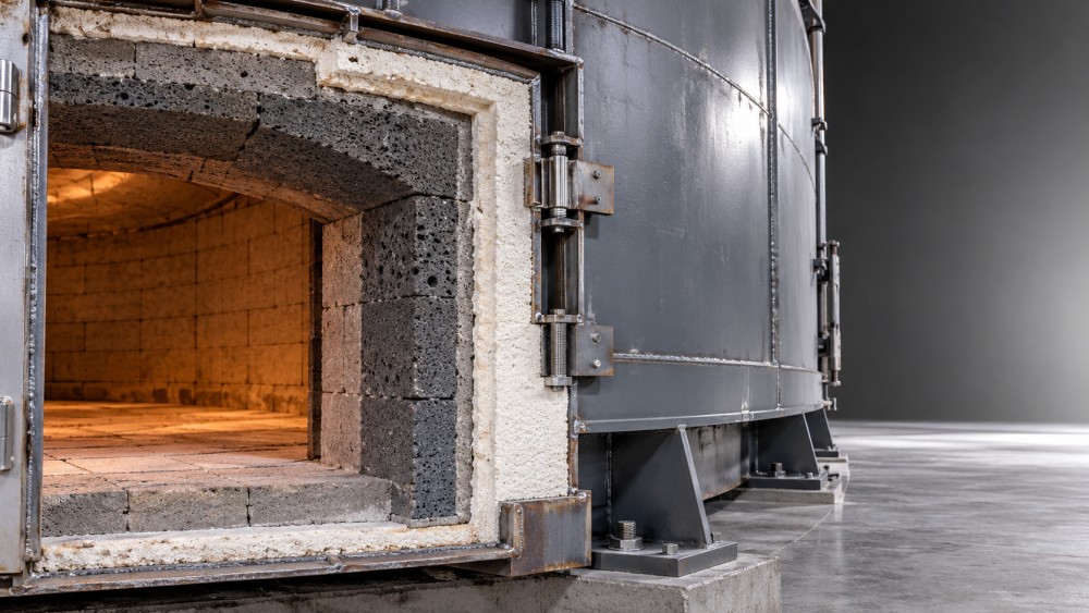
These transitions are common weak points because different materials move differently and installation space is restricted. Continuous coverage around a penetration may matter more than a modest improvement in the conductivity of the main wall insulation.
Cooling practice also affects lining life. Opening doors or introducing cold air can create steep local gradients. When production requires rapid turnaround, assess the proposed lining against that actual cooling cycle rather than assuming a gentle shutdown.
Let process exposure decide what can face the chamber
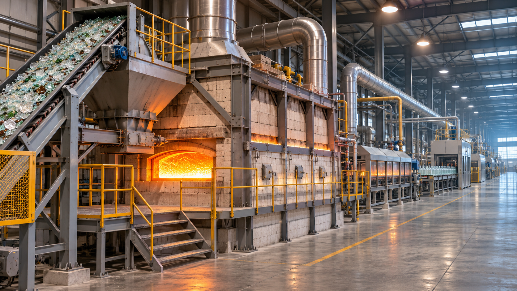
In a relatively clean batch kiln, low thermal mass can reduce the energy needed to reheat the lining. A fiber-based system may suit the walls and roof, while hearth areas require materials capable of supporting the load and resisting damage during loading.
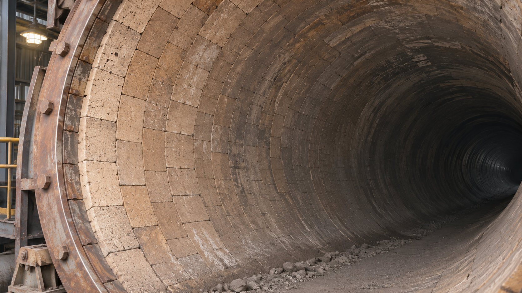
A kiln carrying abrasive solids presents a different problem. An exposed lightweight lining may lose material through impact or erosion even when the temperature remains within its rating. A wear-resistant working face over insulation can provide a more suitable balance, provided the combined structure can accommodate thermal movement.
Chemical compatibility can overturn an otherwise attractive choice. Alkali-bearing deposits, molten glass, ash, and other process materials may react with or penetrate porous refractories. Deposits can also change local heat transfer and create a rigid surface layer that behaves differently from the insulation beneath it.
Assess both the bulk atmosphere and the substances likely to contact the lining. This is especially relevant in incineration and co-processing, where feed changes can alter ash chemistry. A material suitable for a clean combustion chamber may be unsuitable where deposits accumulate.
High gas velocity and direct flame impingement require separate attention. Surface treatments or protective systems may improve resistance in some applications, but they do not replace compatible base materials, suitable burner alignment, and sound lining design.
Balance heat loss against stored heat and usable space
Lower thermal conductivity reduces heat flow through the lining. Lower thermal mass reduces the energy absorbed while the lining heats up. Both influence efficiency, but their relative value changes with the operating schedule.
For a kiln that stays hot for long campaigns, steady heat loss can carry substantial weight in the comparison. For frequent batch operation, energy repeatedly stored in the lining becomes more significant. A durable, dense working face may still be necessary, but its thickness should reflect the mechanical and chemical duty.
Evaluate the complete wall or roof assembly. Include shell heat loss, thermal bridges through anchors and steelwork, doors, joints, and penetrations. More insulation can lower shell temperature while raising the temperature of the working face or internal attachments, so the effects on every layer need checking.
Available space can also change the answer. Adding thickness may reduce chamber volume or affect burner geometry, product clearance, and maintenance access. Where space is limited, a specialty backup material may be useful if its temperature and loading limits fit the design.
Installation quality can determine whether the design works
For castables, water addition, mixing, placement, curing, and dryout affect the installed result. Excess water can alter porosity and strength; inadequate dryout can allow damaging steam pressure to develop during heating. The commissioning schedule must suit the installed lining and its thickest or least ventilated areas.
Fiber systems need consistent module placement, compression, joint treatment, and secure attachment. Brickwork depends on fit, joint thickness, expansion allowances, and stable support. Backup boards need protection against crushing and gaps during assembly.
Specify inspection points before the lining is covered. Check anchor placement, layer thickness, joint continuity, and details around penetrations while they remain accessible. Fiber handling and removal should also follow the product’s safety instructions, with suitable dust control and worker protection.
After commissioning, temperature surveys can reveal localized changes that warrant investigation. Compare readings under similar operating conditions and account for surface emissivity when using thermal imaging. A hot area can indicate a gap, erosion, or a thermal bridge, but the image alone does not identify the cause.
Ask suppliers to evaluate the same duty
A useful quotation describes the proposed assembly and its operating assumptions. Send each supplier the same temperature cycle, atmosphere description, exposure conditions, geometry, and shell-temperature objective. This makes differences in the proposals easier to judge.
Request the following with each proposal:
- Material grades, layer thicknesses, and calculated interface temperatures.
- Conductivity data at relevant temperatures, with density and test conditions identified.
- Permanent dimensional-change data and the conditions used to obtain it.
- Joint, anchor, support, and penetration details suited to the proposed cycle.
- Installation, curing, dryout, inspection, and repair requirements.
- Assumptions about wear, chemical exposure, and foreseeable failure modes.
Compare lifecycle cost across the same operating period. Include installation labor, commissioning downtime, energy use, inspections, repairs, and replacement access alongside material price. A less expensive lining can cost more if frequent patching disrupts production; a premium material adds little value if another weak point limits campaign life.
Before approving the specification, resolve the condition most likely to end the lining’s useful life. That may be shrinkage during long holds, erosion near a burner, chemical penetration beneath deposits, or cracking during rapid cooling. Select the working face to withstand that exposure, then design the insulation, joints, and attachments around it.
Related News
 Ms. Elena RodriguezProcess Equipment Pricing: How to Compare Quotes and Total CostsMaster process equipment comparison pricing: compare supplier quotes, uncover hidden costs, and evaluate lifetime expenses to make a confident buying decision.Nov 17, 2026
 Prof. Marcus ChenGlobal Cement Industry Decarbonization: Key Technologies and Cost BarriersExplore global cement industry decarbonization technologies, cost barriers, and practical investment strategies to cut emissions while protecting competitiveness.Nov 16, 2026
 Structural Material AnalystChoosing Specification Preparation Support for North American ProjectsChoose specification preparation support North America projects can rely on. Compare technical expertise, compliance, interfaces, and supplier acceptance criteria.Nov 14, 2026
 Structural Material AnalystSpecialty Ceramic Extrusion: How Material Properties Affect FormingExplore how ceramic specialized material extrusion is shaped by particle size, binders, and solids loading—and learn to improve forming and reduce defects.Nov 13, 2026
 Ms. Elena RodriguezHigh-Pressure Molding Equipment Prices in Europe: What Affects the Total Cost?Explore high pressure molding equipment price Europe buyers can expect to assess, from tooling and installation to running costs. Compare quotes with confidence.Nov 12, 2026
 Structural Material AnalystChoosing a Vacuum Extrusion System: Capacity, Materials and Vacuum LevelsChoosing a vacuum extrusion system? Compare capacity, material behavior and vacuum levels to improve product quality and select the right equipment.Nov 11, 2026
 Optical Glass Tech FellowGlass Melting Innovations: Comparing Electric and Hybrid Furnace TechnologiesExplore glass melting innovations and compare electric and hybrid furnaces by energy use, emissions, glass quality and operating costs to find the right fit.Nov 10, 2026
 Thermal Energy ArchitectHow Thermal Barrier Technology for Kilns Reduces Heat LossDiscover how thermal barrier technology for kilns reduces heat loss, and learn how to select insulation and assess savings without compromising lining durability.Nov 09, 2026
 Prof. Marcus ChenGlobal Materials Trends: What North American Manufacturers Need to KnowExplore global material trends North America manufacturers need to know, from energy costs and supply chains to lower-carbon materials and smarter investment decisions.Nov 08, 2026
 Thermal Energy ArchitectSelecting Abrasion-Resistant Refractories for High-Wear Kiln LiningsExplore advanced refractory materials abrasion resistant enough for high-wear kiln linings. Compare wear mechanisms, thermal stability, installation and lifecycle costs.Nov 06, 2026
 Dr. Alistair VaughnIndustrial Energy Efficiency Certification: ISO 50001 Requirements for PlantsExplore industrial energy efficiency certification with ISO 50001. Learn how plants define scope, measure performance and prepare credible evidence for audits.Nov 05, 2026
 Ms. Elena RodriguezWhat Is an Industrial Intelligence Database and How Is It Used?Discover how an industrial intelligence database helps researchers map markets, track projects, compare technologies, and assess evidence with confidence.Nov 04, 2026
 Ms. Elena RodriguezIndustrial Material Pricing: How Freight and Order Volume Affect QuotesExplore industrial material pricing and learn how freight, order volume, and inventory costs affect quotes. Compare suppliers and make smarter purchasing decisions.Nov 03, 2026
 Structural Material AnalystSingle- vs. Twin-Screw Extrusion Systems: Which Suits Your Material?Choose the right specialized extrusion systems screw type for your material. Compare single- and twin-screw options to improve quality and control costs.Nov 02, 2026
 Thermal Energy ArchitectChoosing Thermal Barrier Materials for Kilns: Temperature and Heat LossExplore thermal barrier materials for kilns and learn how to balance temperature resistance, heat loss, durability and operating costs when selecting a lining.Nov 01, 2026
 Ms. Elena RodriguezSupplier Reference Platform Pricing: Fees and Contract Terms to CompareCompare supplier reference platform pricing, hidden fees, verification costs and contract terms to choose the right solution for your sourcing team.Oct 31, 2026
 Ms. Elena RodriguezSupplier Comparison Metrics: How to Score Cost, Quality, and DeliveryUse supplier comparison metrics to score cost, quality, and delivery with a practical weighted scorecard. Make more confident equipment sourcing decisions.Oct 30, 2026
 Ms. Elena RodriguezWhat Does Industrial Waste Heat Recovery Cost, and When Does It Pay Back?Understand industrial waste heat recovery cost, from equipment and installation to net savings. Learn how to compare quotes, assess risks, and calculate realistic payback before investing.Oct 29, 2026
 Thermal Energy ArchitectChoosing Industrial Waste-to-Energy Equipment by Waste Moisture and Heating ValueChoose industrial waste to energy equipment by moisture and heating value. Compare technologies, fuel needs, and supplier guarantees to make a confident investment.Oct 28, 2026
 Thermal Energy ArchitectChoosing Industrial Kiln Insulation for High Heat and Repeated Thermal CyclingExplore high temperature industry solutions for kiln insulation under repeated thermal cycling. Compare materials, reduce heat loss, and select the right lining for your operating conditions.Oct 27, 2026

Related News
- 00
0000-00
How Thermal Barrier Technology for Kilns Reduces Heat Loss - 00
0000-00
Selecting Abrasion-Resistant Refractories for High-Wear Kiln Linings - 00
0000-00
Choosing Thermal Barrier Materials for Kilns: Temperature and Heat Loss - 00
0000-00
Choosing Industrial Waste-to-Energy Equipment by Waste Moisture and Heating Value - 00
0000-00
Choosing Industrial Kiln Insulation for High Heat and Repeated Thermal Cycling
0000-00
Weekly Insights
Stay ahead with our curated technology reports delivered every Monday.