
Cement Production Plant Layout Explained: Key Zones, Material Flow, and Bottlenecks




Cement Production Plant Layout Explained: Key Zones, Material Flow, and Bottlenecks
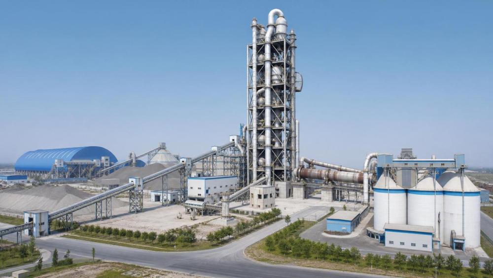
A well-planned cement production plant layout determines far more than equipment placement. It shapes material flow, energy efficiency, dust control, and long-term operating stability.
In practice, layout decisions influence construction cost, maintenance access, and future expansion options. They also affect how easily a plant can meet emissions and throughput targets.
For modern heavy industry, the cement production plant layout is no longer a static drawing. It is a performance model tied to process stability, environmental compliance, and return on capital.
That is why early layout logic matters. A poor arrangement often creates bottlenecks that remain expensive for decades.
Why Layout Logic Matters in Cement Production
Every cement production plant layout must connect raw materials, thermal processing, grinding, storage, and dispatch in one controlled sequence.
When that sequence is compact and balanced, plants reduce rehandling, shorten conveying distances, and avoid unnecessary elevation changes.
The opposite is also true. Weak layout planning can lock a plant into high fan loads, congested traffic routes, and poor maintenance windows.
From a project standpoint, the layout becomes the bridge between process design and site reality. It translates capacity targets into land use, structures, and utility routing.
Core factors that shape layout decisions
- Raw material characteristics, moisture, and variability
- Topography, wind direction, and local environmental limits
- Target kiln size, grinding strategy, and fuel system
- Truck, rail, or port-based inbound and outbound logistics
- Expansion reserve for future lines, WHR, or alternative fuels
Key Zones in a Cement Production Plant Layout
Most layouts follow a linear or semi-linear logic. Materials move from receiving to processing, then to storage and dispatch with minimal backtracking.
A strong cement production plant layout usually includes six functional zones. Each zone should support stable flow and clear operating boundaries.
1. Raw material receiving and crushing
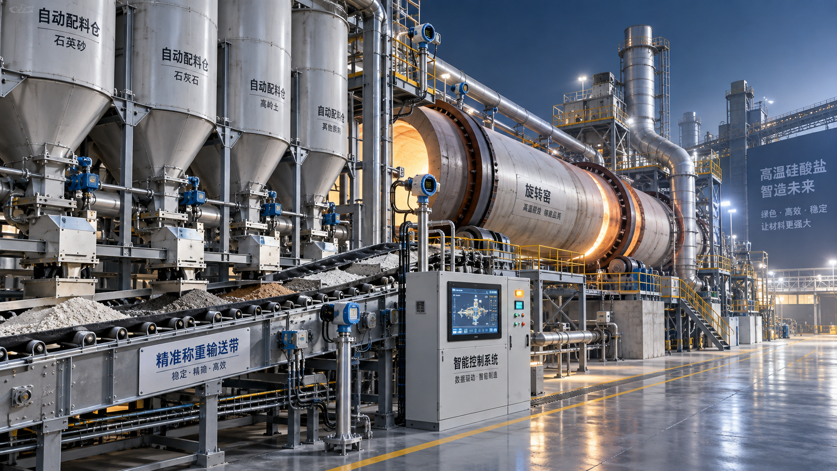
This area handles limestone, clay, corrective materials, and additives. The location should favor easy truck tipping, short feed routes, and dust-contained transfer points.
Crusher placement is critical. If it sits too far from the quarry interface or receiving yard, haulage cost rises quickly.
2. Preblending and raw material storage
This zone stabilizes chemistry before raw milling. Inconsistent pile geometry or reclaim design often leads to feed swings later in the kiln system.
3. Raw mill and homogenization section
The raw mill area must align with gas flow, drying needs, and maintenance access. The blending silo should be close enough to reduce pneumatic and conveying losses.
4. Pyroprocessing zone
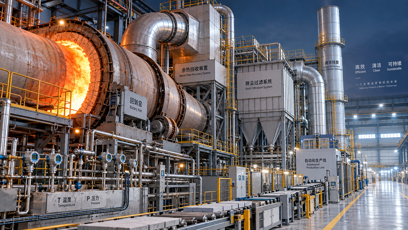
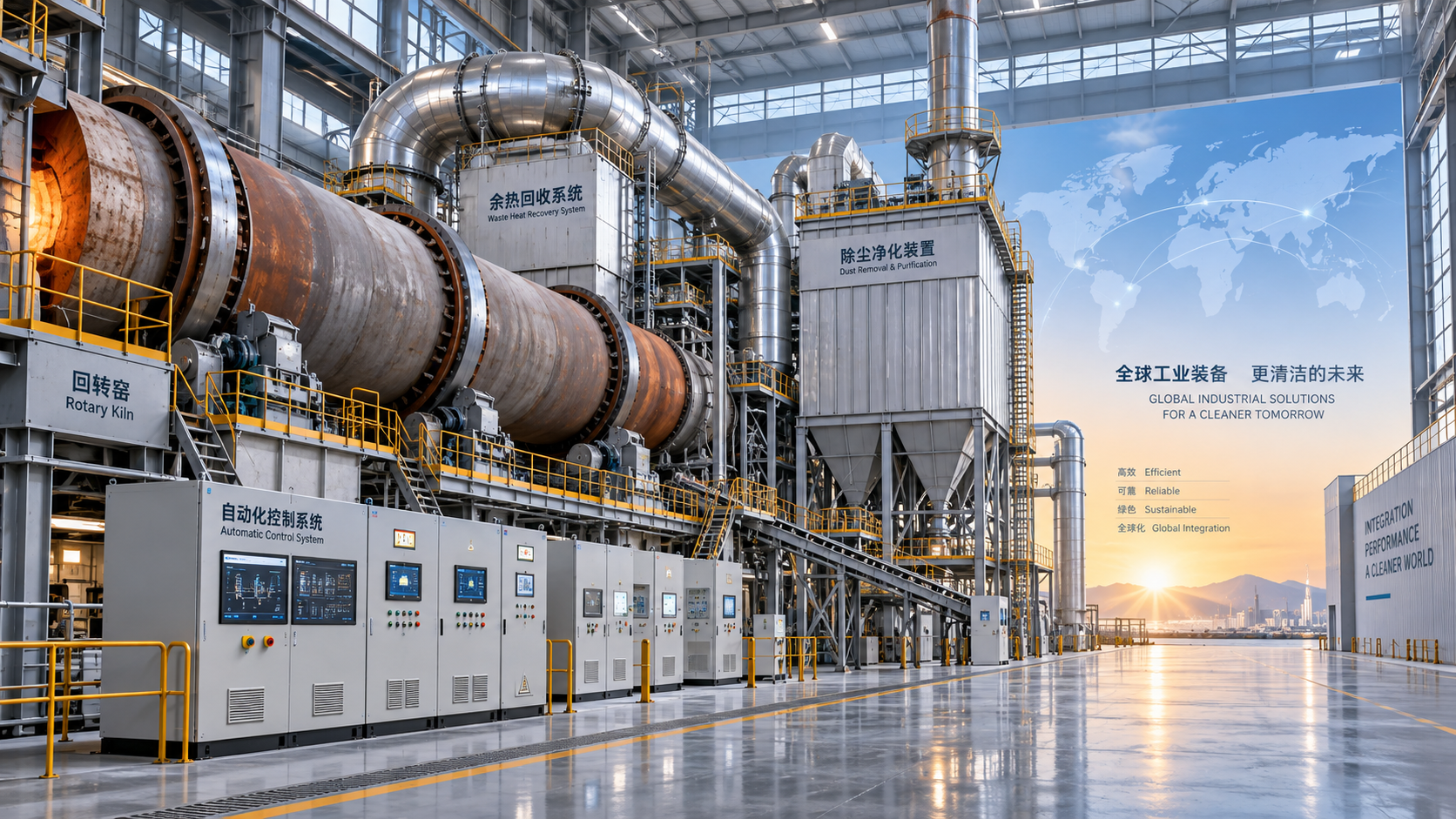
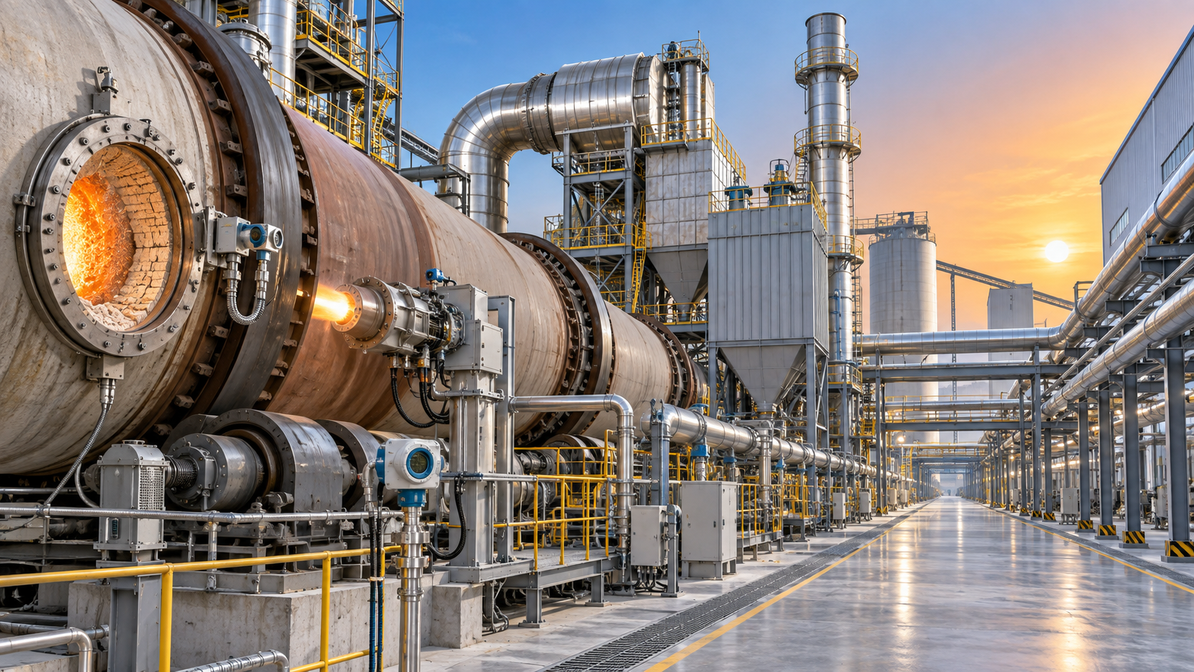
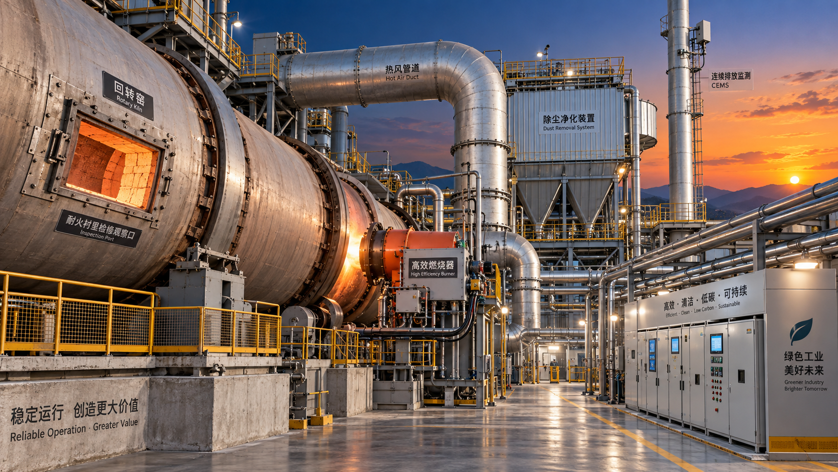
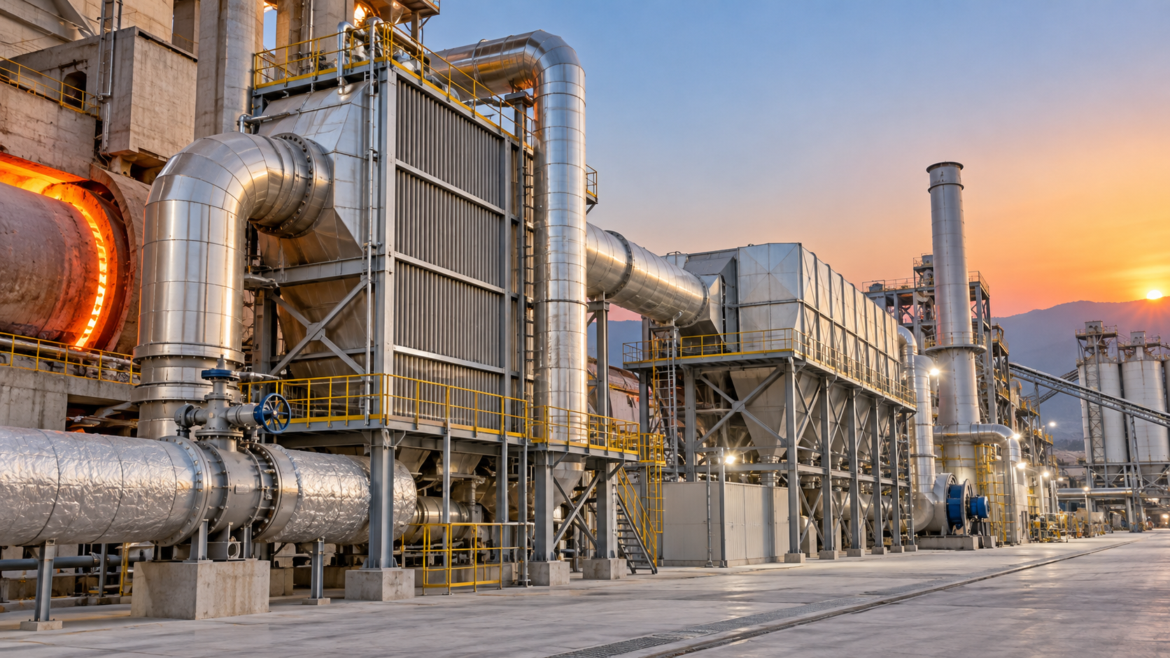
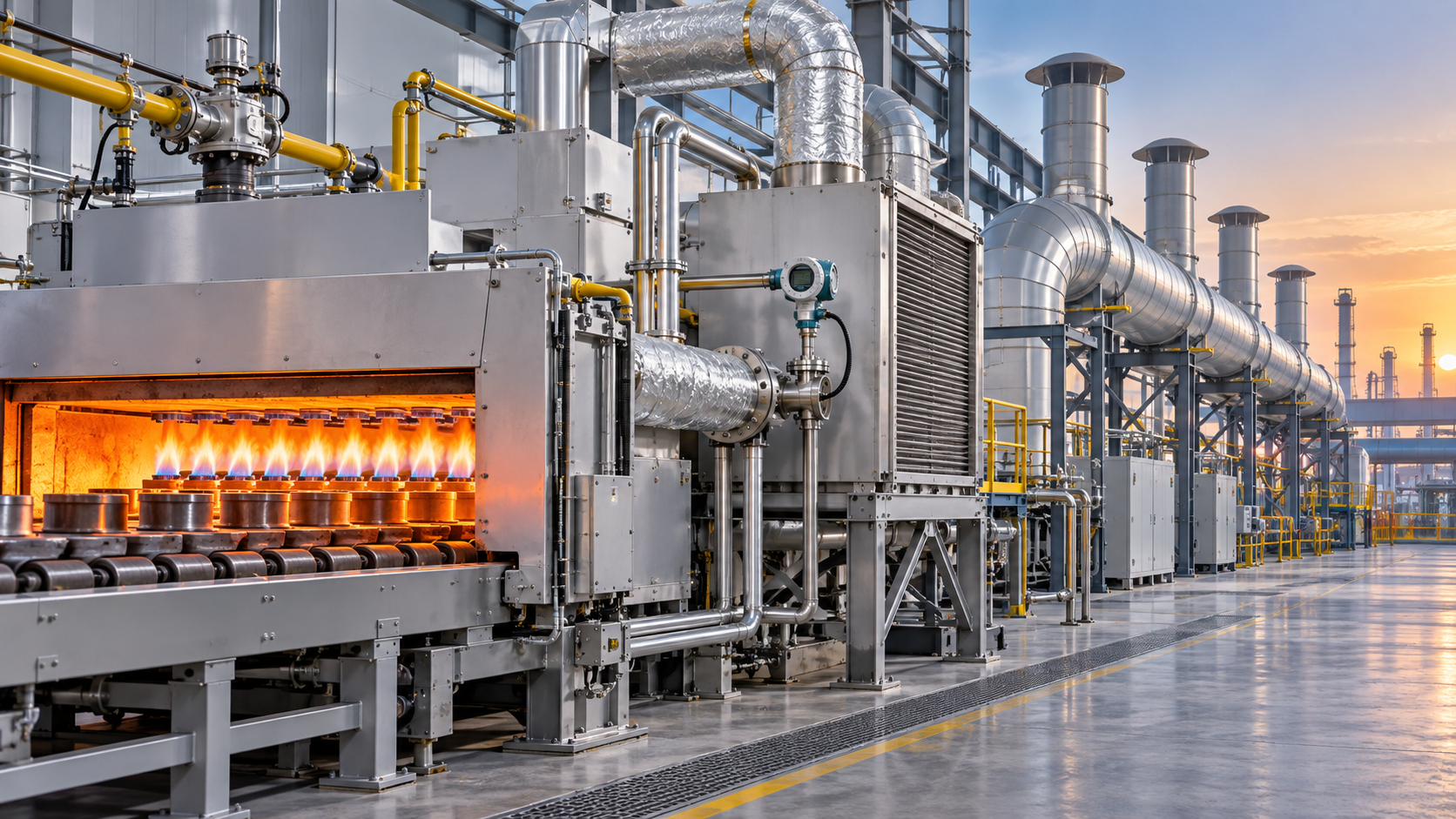
This is the heart of the cement production plant layout. It includes the preheater tower, calciner, rotary kiln, clinker cooler, and major gas handling equipment.
Here, structural spacing must support refractory work, burner access, fan isolation, and safe crane movements.
5. Cement grinding and finished product storage
Clinker, gypsum, and supplementary materials converge in this section. Layout quality directly affects mill feed consistency, additive dosing, and dispatch flexibility.
6. Packing, bulk loading, and logistics
This final zone should separate truck circulation, bagging lines, and bulk loadout. Congestion here can erase gains achieved upstream.
How Material Flow Should Work
The best cement production plant layout keeps material movement predictable, one-directional, and easy to monitor.
At a high level, the flow looks simple. In reality, each transfer point can create loss, delay, dust, or mixing problems.
- Raw materials arrive, are crushed, and move to preblending storage.
- Recovered material feeds the raw mill for drying and grinding.
- Raw meal enters homogenization, then the preheater and calciner.
- The rotary kiln forms clinker, which is cooled and conveyed to storage.
- Clinker mixes with gypsum and additives in the cement mill circuit.
- Finished cement moves to silos, then to bagging or bulk shipment.
Good material flow is not only about speed. It also protects product quality by reducing contamination and unstable residence time.
This is where engineering teams often gain value. Small routing changes can lower transfer losses and improve housekeeping without major process redesign.
What efficient flow usually looks like
- Few direction reversals between major zones
- Minimal crossing between material and vehicle routes
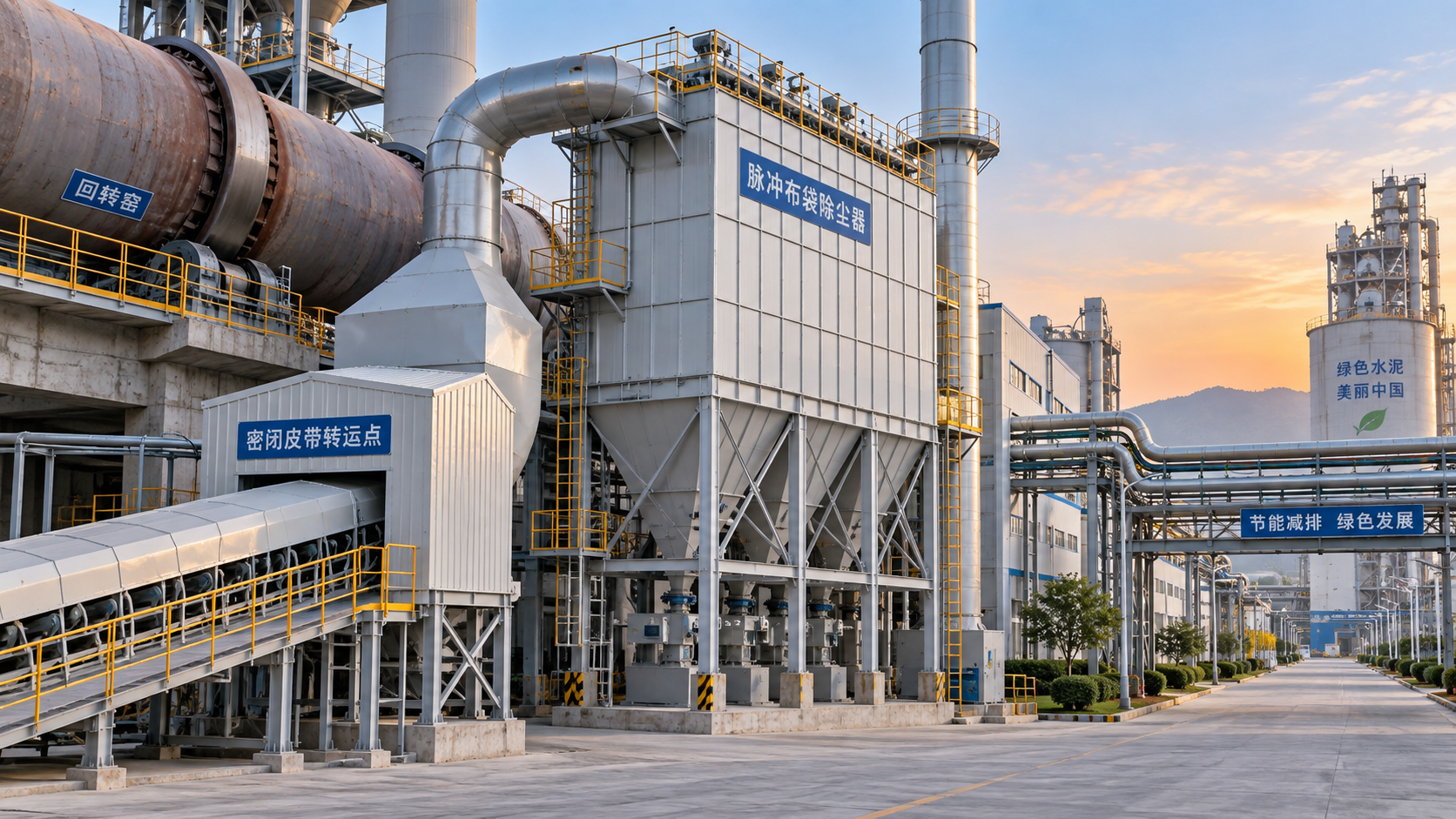
- Short, enclosed conveyors with accessible transfer towers
- Adequate surge capacity before critical process units
- Clear bypass and maintenance isolation points
Common Bottlenecks in Cement Production Plant Layout
Most plant bottlenecks are visible in the layout long before commissioning. The challenge is recognizing them early enough to act.
A cement production plant layout usually fails at transfer interfaces, utility congestion points, or areas where future maintenance was underestimated.
Crushing and preblending bottlenecks
Undersized hoppers, poor truck queuing, and crusher choke feed issues often start here. Wet seasonal material can make the problem much worse.
Raw mill feed instability
Long conveyors, weak dosing arrangements, or difficult sampler access can disturb raw mix quality. That instability then moves downstream into pyroprocessing.
Preheater tower congestion
This is a frequent layout pain point. Overcrowded ducts, platforms, and tertiary air routing can limit inspection space and slow shutdown work.
Clinker transport and storage delays
If the cooler discharge path is long or exposed to repeated transfer failures, kiln stability can suffer. Clinker silo access also needs strong reclaim logic.
Grinding and dispatch mismatch
Plants often optimize production but neglect dispatch throughput. Bagging, palletizing, truck scale flow, and bulk loading then become hidden commercial bottlenecks.
Layout Priorities That Reduce Risk
From recent project patterns, the clearer signal is this: resilient layouts are designed around operability, not only nameplate capacity.
That also means the cement production plant layout should be tested against abnormal conditions, not just ideal mass balance assumptions.
Practical priorities during layout review
- Reserve access for cranes, refractory replacement, and fan extraction
- Separate dusty process zones from office and control traffic
- Limit double handling of raw materials and clinker
- Check elevation changes that increase power demand
- Protect future space for decarbonization upgrades and AFR systems
- Confirm firefighting, emergency escape, and inspection routes early
At CF-Elite, this broader view matters because plant layout now sits inside a larger industrial shift. Energy efficiency, digital monitoring, and carbon pressure are already changing design priorities.
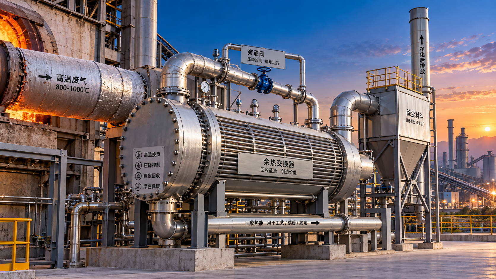
A modern cement production plant layout should therefore leave room for online analyzers, waste heat recovery links, alternative fuel feeding, and tighter emissions control systems.
A Simple Review Framework Before Final Approval
Before locking the general arrangement, use a short review sequence. It helps expose layout weaknesses while changes are still affordable.
- Trace raw material flow from receiving to kiln feed without skipping any transfer point.
- Check whether maintenance teams can remove major components safely.
- Validate dust collection placement against actual emission sources.
- Stress-test truck circulation during peak dispatch periods.
- Review utility corridors for future tie-ins and shutdown isolation.
- Compare storage capacities with kiln and mill continuity targets.
This approach keeps the discussion practical. It moves the layout review away from drawings alone and toward real operating behavior.
Final Takeaway
A strong cement production plant layout combines process logic, site reality, maintenance access, and environmental discipline in one coherent system.
The plants that perform best over time are usually not the most crowded or the most complex. They are the ones where material flow is clear, bottlenecks are anticipated, and expansion remains possible.
When reviewing any cement production plant layout, focus on zone relationships, transfer risk, and serviceability first. Those decisions shape uptime, cost, and compliance long after construction ends.
That is the practical standard worth applying from the earliest design stage to final execution.
Related News
 Optical Glass Tech FellowHow to Evaluate Automated Float Glass Lines for Capacity, Quality, and Energy UseEvaluate automated float glass lines for net capacity, consistent quality, energy efficiency, automation reliability, and lifecycle value. Explore key criteria for smarter investment decisions.Oct 05, 2026
 Thermal Energy ArchitectWhat Does CE Marking Require for an Energy-Efficient Industrial Kiln?Energy efficient kiln CE requirements explained: assess safety, technical files, energy performance, and EU compliance before purchase or commissioning.Oct 04, 2026
 Thermal Energy ArchitectRefractory Manufacturing Solutions for Brick Plants: How to Extend Kiln LifeRefractory manufacturing solutions for brick plant operations: discover proven strategies to extend kiln life, reduce heat loss, prevent lining failures, and plan cost-effective repairs.Oct 03, 2026
 Thermal Energy ArchitectHow to Specify Heavy Industrial Process Systems for High-Temperature PlantsHeavy industrial processes systems: learn how to specify high-temperature plants for efficiency, emissions control, maintainability, and lifecycle performance.Oct 02, 2026
 Structural Material AnalystHow Sustainable Material Extrusion Can Improve Wall Panel Durability and Design FlexibilityDiscover how sustainable material extrusion for wall panels improves durability, moisture resistance, design flexibility, and installation consistency for high-performing wall systems.Oct 01, 2026
 Thermal Energy ArchitectHow to Evaluate a High-Temperature Materials Manufacturer for Furnace ApplicationsChoose a high-temperature materials manufacturer with confidence: compare thermal performance, chemical resistance, quality controls, installation support, and lifecycle cost.Sep 30, 2026
 Ms. Elena RodriguezHow to Structure Global Specification Data for Faster Industrial Product EvaluationGlobal specification-oriented product information helps industrial teams compare capacity, energy, emissions, automation, and lifecycle data on a like-for-like basis for faster, confident equipment decisions.Sep 29, 2026
 Thermal Energy ArchitectHow to Specify High-Temperature Process Systems for Continuous Thermal OperationsHigh-temperature process engineering systems: learn how to specify resilient continuous thermal operations for efficiency, compliance, reliable uptime, and long-term performance.Sep 28, 2026
 Thermal Energy ArchitectHow to Evaluate a Thermal Engineering Contractor for High-Temperature Plant ProjectsChoose a thermal engineering contractor with proven process expertise, lifecycle value, emissions control, and delivery discipline for reliable high-temperature plant performance.Sep 27, 2026
 Silicate Process EngineerHow Latin American Cement Plants Can Reduce Dust Emissions in Kilns and Transfer PointsCement plant dust control Latin America: reduce kiln and transfer-point emissions with practical airflow, filtration, monitoring, and maintenance strategies.Sep 26, 2026
 Material Heat-Resist ExpertHow to Evaluate Refractory Production Lines for Output, Quality, and Energy UseRefractory production lines: learn how to assess qualified output, consistent quality, and total energy use for smarter, lower-risk investment decisions.Sep 25, 2026
 Dr. Alistair VaughnHow Waste Recycling Technology Improves Material Recovery in Industrial PlantsWaste recycling technology improves material recovery through source segregation, smart separation, thermal treatment, and quality control for industrial plants.Sep 24, 2026
 Optical Glass Tech FellowHow to Specify Glass Annealing Equipment for European Quality and Energy RequirementsGlass annealing equipment Europe: learn how to specify lehrs for consistent glass quality, energy efficiency, compliance, automation, and reliable long-term performance.Sep 23, 2026
 Optical Glass Tech FellowSilicate Process Automation: Improving Batch Consistency and Energy ControlSilicate process automation improves batch consistency, energy control, traceability, and operator confidence across high-temperature manufacturing operations.Sep 22, 2026
 Optical Glass Tech FellowHow Silicate Industrial Processes Control Viscosity, Energy Use, and Product QualitySilicate industrial processes: learn how viscosity, chemistry, heat transfer, and atmosphere control reduce energy use, improve stability, and protect product quality.Sep 21, 2026
 Thermal Energy ArchitectHow European Plants Can Evaluate Energy Recovery Equipment for High-Temperature ProcessesIndustrial energy recovery equipment Europe: learn how high-temperature plants can assess waste-heat sources, integration risks, lifecycle value, and reliable recovery routes.Sep 20, 2026
 Thermal Energy ArchitectIndustrial Furnace Process Optimization: Reducing Fuel Use Without Sacrificing ThroughputIndustrial process optimization furnace strategies that cut fuel use while protecting throughput. Explore combustion control, heat recovery, refractory performance, and data-driven efficiency gains.Sep 19, 2026
 Ms. Elena RodriguezWhat Drives High-Pressure Extrusion Equipment Cost in Industrial Projects?High pressure extrusion equipment cost explained: compare pressure, die design, automation, wear, energy, and installation factors for smarter industrial investments.Sep 18, 2026
 Thermal Energy ArchitectHow to Size a Waste Heat Recovery Exchanger for High-Temperature Kiln Exhaust?Waste heat recovery exchanger sizing for high-temperature kiln exhaust: balance recoverable duty, fouling, corrosion limits, pressure drop, and reliable heat use.Sep 17, 2026
 Thermal Energy ArchitectWhy Heat-Resistant Materials Lose Abrasion Resistance at High TemperaturesHeat-resistant materials abrasion resistance can decline at high temperatures. Discover the thermal, chemical, and mechanical causes of wear—and how to choose longer-lasting linings.Sep 16, 2026

Related News
- 00
0000-00
How Latin American Cement Plants Can Reduce Dust Emissions in Kilns and Transfer Points - 00
0000-00
Cement Plant Emission Control: Selecting Systems for Dust, NOx, and SO2 Limits - 00
0000-00
Cement Production System Costs: A Plant Buyer’s Guide to Budgeting and ROI - 00
0000-00
How Kiln Heat Recovery Systems Cut Fuel Use in Cement and Lime Production - 00
0000-00
How to Evaluate Cement Production Plants in the Middle East for Capacity, Fuel Flexibility, and ROI
Weekly Insights
Stay ahead with our curated technology reports delivered every Monday.