
How to Size a Waste Heat Recovery Exchanger for High-Temperature Kiln Exhaust?




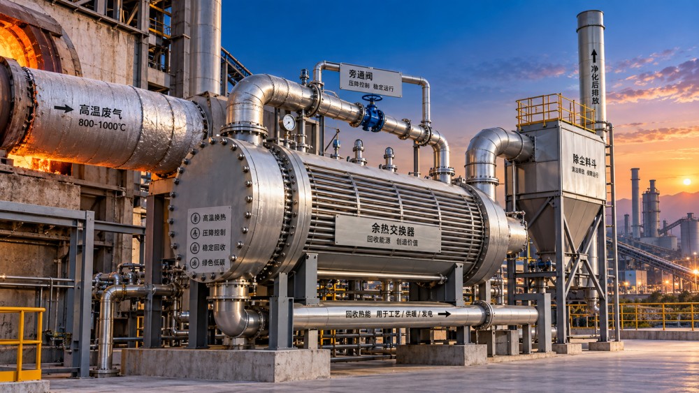
A high-temperature kiln exhaust exchanger should be sized around the heat that can be recovered reliably at acceptable process risk, not around the highest temperature visible in a stack reading. A large theoretical duty can look attractive in a preliminary energy balance yet prove unusable once dust deposition, gas-side pressure loss, acid condensation limits, and variable kiln operation are included.
For technical evaluators, the practical question is: how much heat can be transferred over the operating envelope without disturbing draft control, creating an unmanageable cleaning burden, or delivering a temperature level that the downstream user cannot use? The answer begins with a disciplined heat balance, then narrows through gas chemistry, fouling behavior, exchanger geometry, materials, and control philosophy.
Start With the Recoverable Duty, Not the Nameplate Exhaust Temperature
The first calculation is straightforward in form:
Q = m x Cp x (Tin - Tout)
Where Q is recoverable heat duty, m is exhaust mass flow, Cp is the effective specific heat of the gas stream, and the temperature difference is the intended cooling range. In kiln service, however, every term must be treated as a range rather than a single design value.
Exhaust flow can vary with kiln feed rate, excess air, false-air ingress, fuel changes, bypass operation, raw-material moisture, induced-draft fan control, and process interruptions. The gas composition affects both mass flow and heat capacity. A calculation based only on a nominal volumetric flow at one temperature can therefore oversize or undersize the exchanger substantially.
The useful starting dataset should include measured or defensible operating envelopes for:
- Minimum, normal, and maximum exhaust temperature at the proposed exchanger location.
- Gas mass flow or normalized volumetric flow across corresponding operating states.
- Oxygen, moisture, carbon dioxide, and relevant contaminant concentrations.
- Dust concentration, particle-size characteristics, and whether the dust is sticky, abrasive, or prone to sintering.
- Permitted gas outlet temperature and the downstream heat sink's required inlet temperature.
- Available draft margin and the maximum additional pressure drop that the kiln system can tolerate.
A useful heat-recovery design commonly uses normal operation as the economic reference case, while checking maximum and minimum states for mechanical and process limits. Designing solely for the hottest recorded exhaust condition often creates excess surface area that performs poorly for much of the year. Designing only for average conditions can leave the system unable to protect itself during hot, dusty, or high-flow events.
The selected cold-side duty must be equally specific. Heat for combustion-air preheating, boiler feedwater heating, drying, district heating, thermal-oil service, and power generation does not have the same value merely because each consumes the same number of kilowatts. The required delivery temperature, seasonal load profile, startup availability, and tolerance for interruptions determine how much exhaust cooling is sensible.
For example, a downstream water circuit may accept a large quantity of moderate-temperature heat, while a combustion-air application may require a smaller flow at a higher outlet temperature. The latter can impose a tighter hot-end temperature approach and a different exchanger arrangement. The heat sink should be defined before surface area is calculated.
Set the Gas Outlet Temperature as a Process and Corrosion Limit
The exhaust outlet temperature is often the most consequential design decision. Lowering it increases theoretical recovery, but only until the added surface, fouling exposure, corrosion risk, and fan power outweigh the useful energy gain.
High-temperature kiln exhaust may contain combinations of water vapor, sulfur-bearing compounds, chlorides, alkalis, fluorides, unburned species, and fine mineral dust. The composition depends heavily on feed, fuel, alternative-fuel use, bypass configuration, and gas take-off point. Cooling such gas can bring local metal surfaces below a condensation threshold even where the calculated bulk gas outlet temperature appears acceptable. Deposits can then become wet, corrosive, and far harder to remove.
This is why bulk-temperature design alone is inadequate. The supplier's thermal model should show predicted tube-wall or plate-wall temperatures in the coldest regions, especially during low-load operation, cold-side startup, and transient conditions. A system that maintains an acceptable average outlet temperature may still have cold-end zones vulnerable to condensed corrosive species.
There is no universal safe outlet temperature for kiln exhaust. It must be established from the expected chemical envelope and validated against the intended equipment arrangement. Evaluators should be cautious when a proposal uses a fixed corrosion margin without documenting the gas composition assumptions behind it.
Where deeper cooling has material value, staged recovery is often more defensible than asking one exchanger to span the entire temperature drop. A high-temperature first stage can recover robust heat while keeping surfaces above the most problematic low-temperature range. A downstream stage, if justified, can use different materials, a different heat-transfer medium, or a bypass arrangement suited to cold-end protection.
Size Heat-Transfer Area With Fouling as a Primary Design Input
Once duty and temperature targets are defined, required surface area is generally derived from:
Q = U x A x LMTD x F
Here, U is the overall heat-transfer coefficient, A is heat-transfer area, LMTD is the log-mean temperature difference, and F is a correction factor for the flow arrangement. The equation is familiar; the risk lies in assigning an unrealistically high value of U.
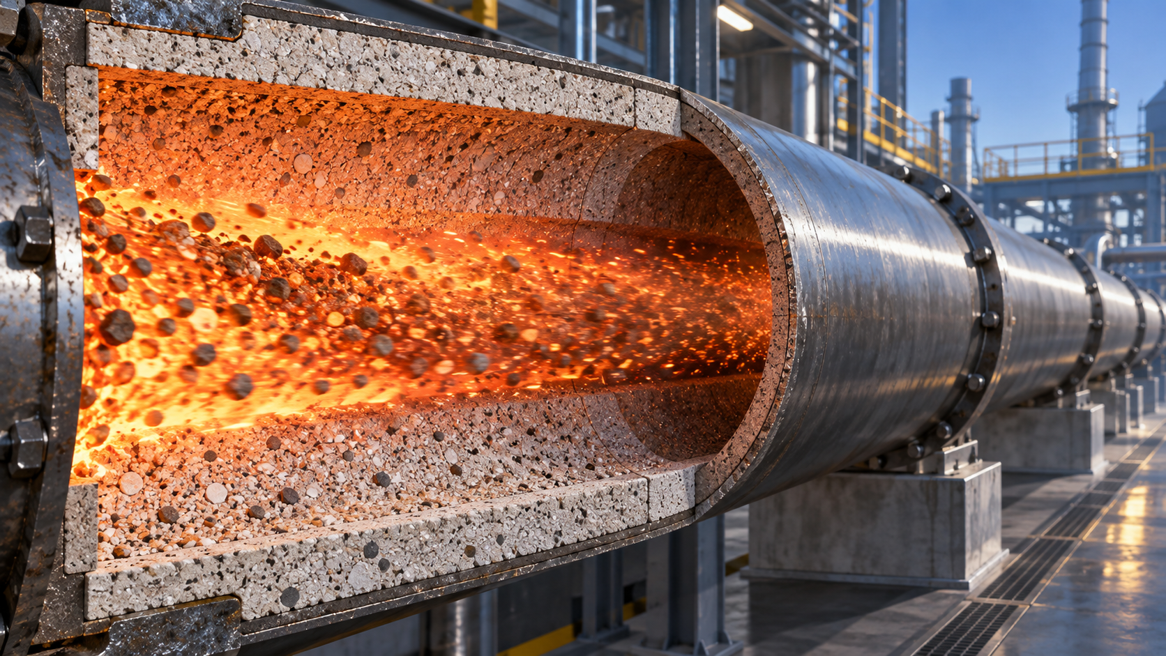
In clean gas service, an optimistic coefficient may yield a compact design. Kiln exhaust is rarely clean gas service. Dust layers add thermal resistance, alter flow paths, and can accumulate unevenly. In some services, deposits are loose and removable with sootblowing or rapping. In others, alkali-rich or partially fused deposits form bridges between tubes, block passages, and change local gas velocity. Abrasive particles can also erode leading edges and thin heat-transfer surfaces over time.
Fouling allowance should therefore be tied to a clear operating concept, not inserted as a generic percentage. The evaluator should ask:
- What dust mass and particle characteristics were assumed at the exchanger inlet?
- Is a pre-separator, settling chamber, cyclone, or other conditioning step required before the exchanger?
- What gas velocity is used through the bundle or channels, and how does it balance deposition against erosion and pressure loss?
- How will deposits be removed: online cleaning, offline washing, rapping, acoustic cleaning, sootblowing, or manual access?
- Can the selected cleaning method reach the zones most likely to foul?
- What performance condition defines cleaning intervention: pressure-drop rise, outlet-temperature drift, heat-duty loss, or visual inspection?
A design with more compact passages is not automatically better. It can offer a smaller footprint and lower initial material use, but narrow flow channels are less forgiving of particulate loading and may make cleaning ineffective. Wider pitch, accessible tube bundles, suitable gas velocities, and deliberate ash-hopper geometry may cost more initially while preserving availability.
The distinction matters especially where the kiln's production schedule does not tolerate frequent outages. If cleaning requires a shutdown, the assessment should include the operational cost of lost thermal recovery and the potential process disruption, rather than comparing capital cost alone.
Pressure Drop Is Part of Kiln Stability
Every waste heat recovery exchanger extracts energy in two ways: thermally from the gas and mechanically from the draft system. More surface area, tighter passages, and higher gas velocity can improve heat transfer, but they also increase resistance. On a kiln line, that resistance is carried by the induced-draft system and can affect pressure balance upstream.
The acceptable gas-side pressure drop must be established with the process engineer and fan data, not selected as an isolated exchanger specification. Existing fan capacity, damper position, fan-control range, dust collection equipment, bypass ducts, and upset conditions all matter. A proposal may meet heat-duty requirements on paper while consuming the reserve required to maintain stable kiln draft during high-flow operation or when deposits raise resistance.
Review pressure drop at clean and fouled conditions. The clean figure matters for energy consumption, but the fouled figure is often the more useful availability test. Ask how the design model treats deposit growth, whether the fan can cover that condition, and what automatic response occurs if differential pressure rises faster than expected.
Bypass dampers are frequently necessary, but they should be treated as protective equipment rather than evidence that the core design can tolerate any condition. A bypass should respond to high gas temperature, cold-side upset, high differential pressure, cleaning cycles, and maintenance needs without creating uncontrolled thermal shock or unstable draft. Its sealing performance and fail position deserve the same scrutiny as the exchanger itself.
Choose the Exchanger Configuration Around the Exhaust Character
There is no single preferred configuration for high-temperature kiln exhaust. Selection depends on the combination of temperature, solids loading, required heat sink, maintenance access, corrosion exposure, and pressure-drop allowance.
Material selection follows from local metal temperature and chemistry, rather than bulk inlet temperature alone. High-temperature strength, oxidation resistance, chloride and sulfur exposure, abrasion, weldability, and replacement strategy can point toward different material choices in different zones. The cold end may need more attention than the visibly hottest section if corrosive condensation is credible there.
Thermal expansion also deserves a direct design review. Kiln exhaust temperature can change quickly during startup, stoppage, fuel changes, false-air events, and process disturbances. Supports, expansion joints, tube-to-header connections, casing design, and insulation must accommodate those movements. Repeated thermal cycling can be as influential on service life as steady-state temperature.
Evaluate the Proposal With an Operating Envelope, Not a Single Guarantee Point
A vendor guarantee at one gas flow, one inlet temperature, and a clean-surface condition is insufficient for a selection decision. The technical package should show predicted duty, outlet temperatures, pressure drop, and metal-temperature limits across a matrix of operating cases. At minimum, review normal load, maximum gas temperature, maximum gas flow, low-load operation, cold-side low-flow operation, and a fouled condition.
The calculation basis should identify what is measured, what is assumed, and what design margin has been applied. Important assumptions include gas composition, dust concentration, allowable air leakage, fouling resistance, cleaning effectiveness, cold-side inlet temperature, and fan capability. Unstated assumptions become project risk when operating data later differs from the proposal basis.
Control and instrumentation should support the thermal design. Gas inlet and outlet temperatures, cold-side supply and return temperatures, differential pressure, flow where practical, and bypass position provide the minimum visibility needed to distinguish a process change from exchanger fouling. High-temperature alarms alone do not protect a cold-end corrosion problem; differential-pressure trends alone do not reveal declining heat transfer caused by insulating deposits.
Technical evaluators should also separate recoverable heat from usable heat. A large annual heat figure has limited value if the receiving process is unavailable during kiln operation, if the energy arrives at an unusable temperature, or if the system must bypass frequently to protect the line. Storage, alternate consumers, turndown, and seasonal demand can alter the preferred size more than a marginal improvement in calculated exchanger effectiveness.
A Defensible Sizing Decision
The strongest sizing basis is usually a constrained optimization: recover the heat that has a stable downstream use, maintain outlet and wall temperatures within a chemistry-informed operating window, keep pressure drop inside the kiln draft margin at fouled condition, and provide cleaning and bypass arrangements that can be operated without improvisation.
Before release for purchase, require the thermal model, gas and dust design basis, pressure-drop curve, fouling and cleaning philosophy, materials schedule by temperature zone, thermal-expansion provisions, and the control response for upset cases. Those documents reveal whether the proposed waste heat recovery exchanger is designed for kiln exhaust as it behaves in service, rather than for an idealized hot-gas stream.
Related News
 Thermal Energy ArchitectHow to Size a Waste Heat Recovery Exchanger for High-Temperature Kiln Exhaust?Waste heat recovery exchanger sizing for high-temperature kiln exhaust: balance recoverable duty, fouling, corrosion limits, pressure drop, and reliable heat use.Sep 17, 2026
 Thermal Energy ArchitectWhy Heat-Resistant Materials Lose Abrasion Resistance at High TemperaturesHeat-resistant materials abrasion resistance can decline at high temperatures. Discover the thermal, chemical, and mechanical causes of wear—and how to choose longer-lasting linings.Sep 16, 2026
 Thermal Energy ArchitectHow to Evaluate a Thermal Energy Optimization Company for High-Temperature PlantsChoose a thermal energy optimization company with proven process expertise, measurable savings, and reliable delivery for high-temperature plants. Learn what to assess.Sep 15, 2026
 Thermal Energy ArchitectRotary Kiln Efficiency: How Feed Rate, Fuel Use, and Heat Loss Affect OutputRotary kiln efficiency explained: discover how feed rate, fuel use, heat loss, combustion, and cooling performance shape output, quality, and energy costs.Sep 14, 2026
 Thermal Energy ArchitectHow to Select Heat-Resistant Materials That Maintain Abrasion Resistance in KilnsHeat-resistant materials abrasion resistance: learn how to select kiln linings that withstand heat, wear, thermal cycling, and chemical attack for longer service life.Sep 13, 2026
 Thermal Energy ArchitectHow Rotary Kiln Automation Improves Temperature Control and Fuel EfficiencyRotary kiln technology automation enhances temperature control, stabilizes combustion, and improves fuel efficiency with smarter data, predictive control, and safer operations.Sep 12, 2026
 Silicate Process EngineerCement Plant Emission Control: Selecting Systems for Dust, NOx, and SO2 LimitsCement plant emission control guide: compare dust collectors, NOx reduction, and SO2 systems for reliable compliance across kiln modes, fuel changes, and operating upsets.Sep 11, 2026
 Thermal Energy ArchitectSelecting Abrasion-Resistant High-Temperature Materials for Kiln and Conveyor Wear ZonesHigh-temp material engineering guide to abrasion-resistant kiln and conveyor solutions—match wear, heat, chemistry, and installation design for longer service life.Sep 10, 2026
 Dr. Alistair VaughnIndustrial Process Engineering: How to Map Processes for Safer, More Efficient PlantsIndustrial process engineering reveals bottlenecks, safety risks, and energy losses through practical process mapping for safer, more efficient plants.Sep 09, 2026
 Optical Glass Tech FellowHow to Evaluate a Glass Annealing Equipment Manufacturer for Production StabilityChoose a glass annealing equipment manufacturer with proven thermal uniformity, reliable controls, lifecycle value, and responsive service for stable production.Sep 08, 2026
 Prof. Marcus ChenThermal Energy Architecture in North America: Strategies for Lower Building Energy UseThermal energy architecture North America helps project leaders cut building energy use through stronger envelopes, right-sized HVAC, storage, and smart commissioning.Sep 07, 2026
 Ms. Elena RodriguezHow Should Buyers Evaluate Building Material Industry Intelligence Pricing?Building material industry intelligence pricing: learn how to compare coverage, technical depth, and ROI to choose intelligence that reduces procurement risk.Sep 07, 2026
 Ms. Elena RodriguezHow to Use Building Material Intelligence Data for Market and Investment DecisionsBuilding material industry intelligence data helps leaders evaluate demand, costs, regulation, capacity, and technology to make smarter market and investment decisions.Sep 05, 2026
 Thermal Energy ArchitectHow PLC Control Improves Energy Efficiency and Temperature Stability in KilnsEnergy efficient kilns PLC control improves temperature stability, cuts fuel waste, and optimizes combustion, draft, and material flow. Explore proven strategies for smarter kiln modernization.Sep 04, 2026
 Optical Glass Tech FellowEuropean Glass Melting Processes: Furnace Choices, Energy Use, and Quality ControlGlass melting process Europe: explore furnace choices, energy efficiency, cullet strategy, and quality control to improve output, compliance, and long-term glass performance.Sep 03, 2026
 Thermal Energy ArchitectWhat Determines Refractory Lining Monitoring Price for Industrial Kilns?Refractory lining monitoring price depends on kiln size, sensor technology, installation, software, and support. Compare total lifecycle costs and choose the right solution.Sep 02, 2026
 Silicate Process EngineerCement Production System Costs: A Plant Buyer’s Guide to Budgeting and ROICement production systems cost planning made clear: compare CAPEX, operating costs, compliance, and ROI to build a resilient, profitable cement plant investment.Sep 01, 2026
 Dr. Alistair VaughnWhat Should a Process Technology Database Track for High-Temperature Plants?Process technology database essentials for high-temperature plants: track thermal profiles, feed chemistry, refractory wear, emissions, energy, and maintenance for safer, data-driven decisions.Aug 31, 2026
 Ms. Elena RodriguezHow to Evaluate a Silicate Processing Equipment Manufacturer for Plant ProjectsSilicate processing equipment manufacturer selection: assess process fit, guarantees, energy, compliance, delivery risk, and lifecycle support for dependable plant performance.Aug 30, 2026
 Dr. Alistair VaughnHow to Specify Custom Agricultural Processing Equipment for Throughput and HygieneEquipment customization services for agricultural processing: learn to specify hygienic, high-throughput lines that improve yield, reliability, and long-term efficiency.Aug 29, 2026



Related News
- 00
0000-00
How to Size a Waste Heat Recovery Exchanger for High-Temperature Kiln Exhaust? - 00
0000-00
Why Heat-Resistant Materials Lose Abrasion Resistance at High Temperatures - 00
0000-00
How to Evaluate a Thermal Energy Optimization Company for High-Temperature Plants - 00
0000-00
Rotary Kiln Efficiency: How Feed Rate, Fuel Use, and Heat Loss Affect Output - 00
0000-00
How to Select Heat-Resistant Materials That Maintain Abrasion Resistance in Kilns
Weekly Insights
Stay ahead with our curated technology reports delivered every Monday.