
How European Plants Can Evaluate Energy Recovery Equipment for High-Temperature Processes




Selecting industrial energy recovery equipment in Europe for a kiln, furnace, glass line, incinerator, or refractory process begins with one question: can the plant use the recovered energy reliably at the time and temperature at which it becomes available?
A system can look attractive on a heat-balance diagram yet underperform after installation because the exhaust stream is unstable, dust-laden, corrosive, poorly located, or disconnected from a useful heat demand. Purchase price and nominal recovery capacity matter, but they are not the decision point. The practical evaluation is about matching a real waste-heat source to a real, continuous energy sink while preserving production uptime, product quality, and emissions control.
Start with the heat source, not the equipment catalogue
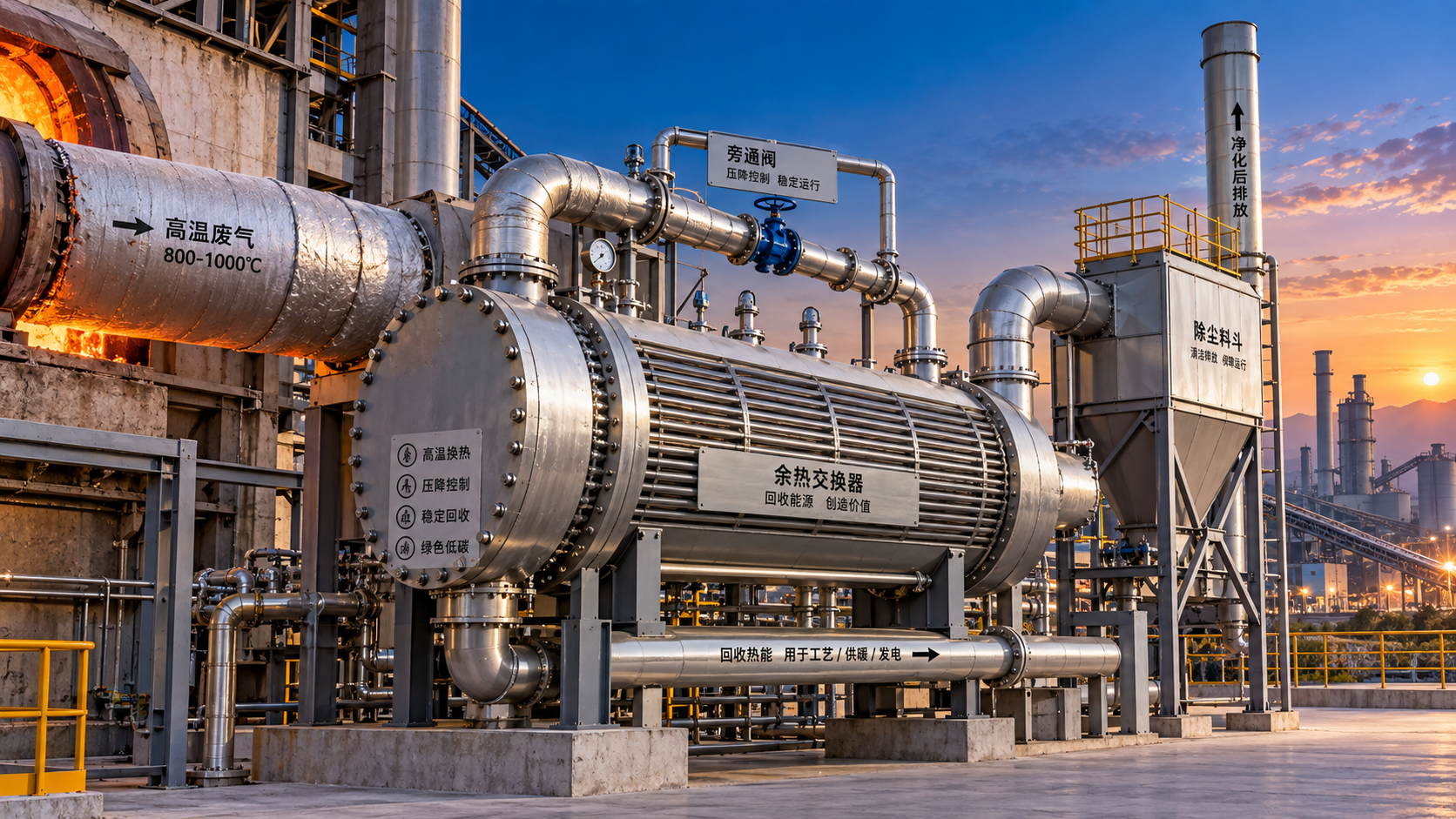
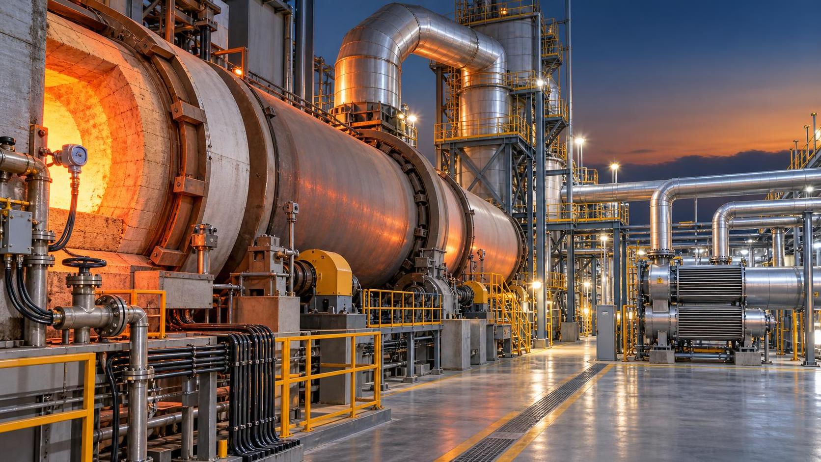
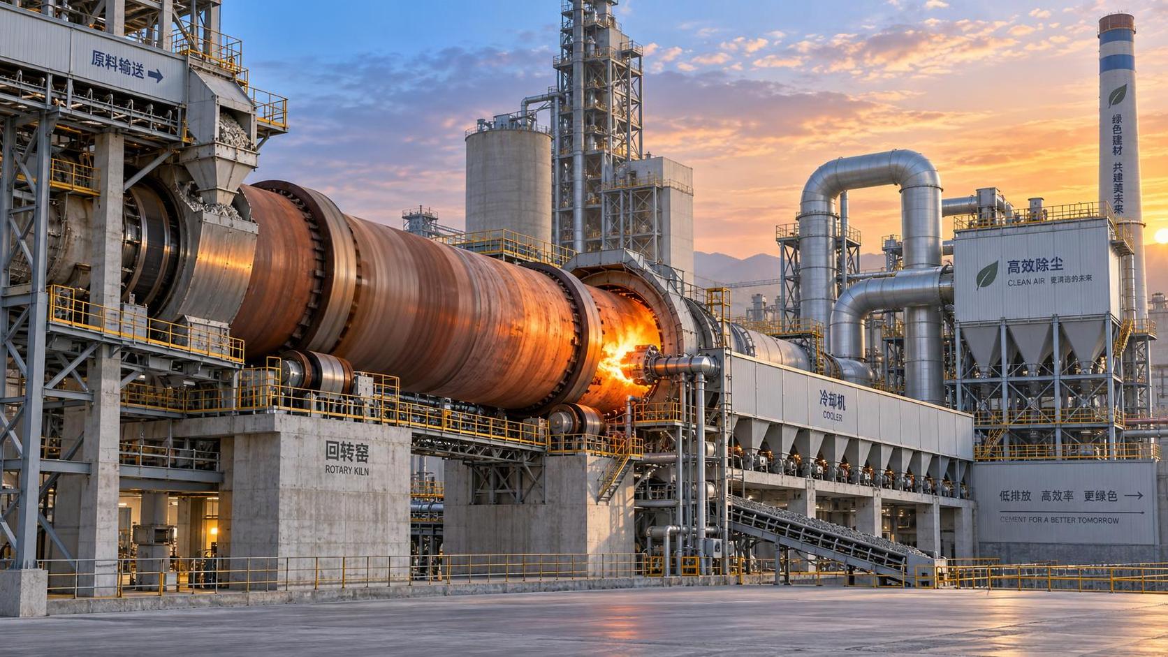
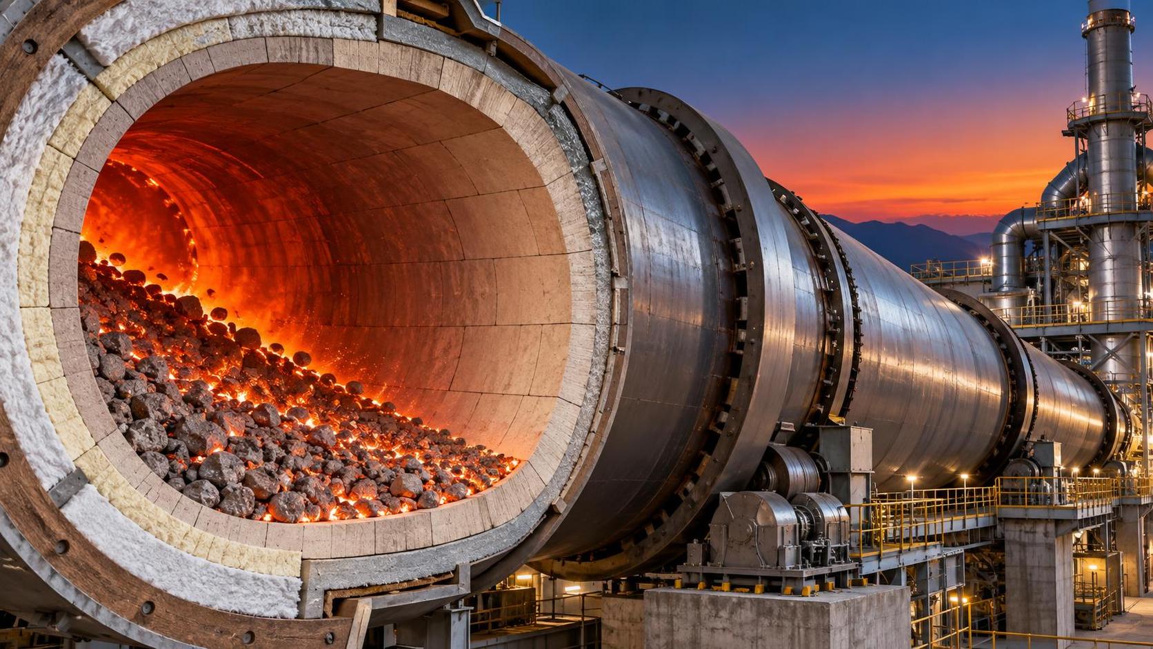
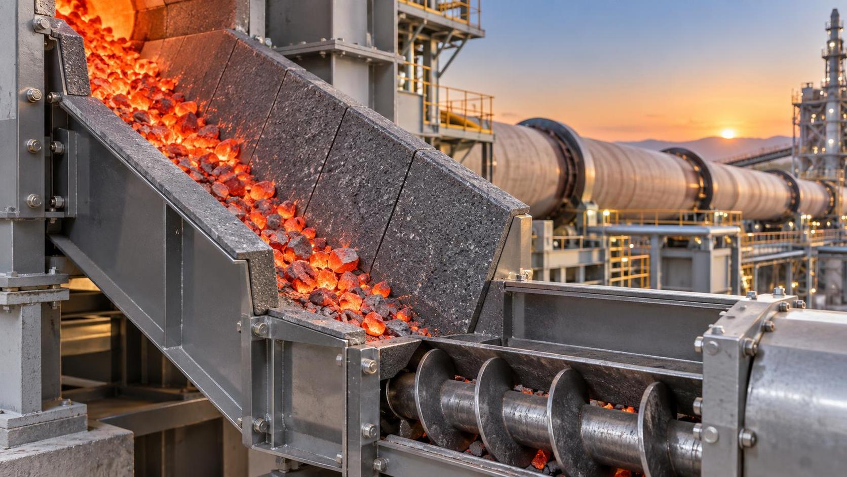
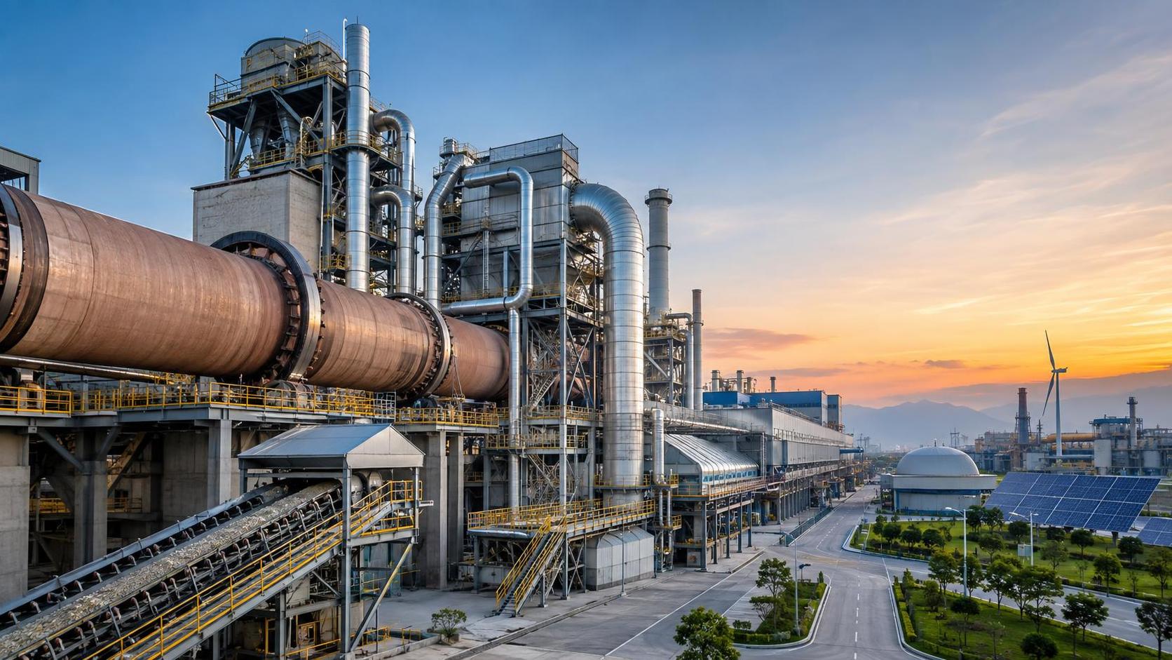
High-temperature processes do not produce a uniform “waste heat” resource. A rotary kiln exhaust, furnace flue gas, clinker cooler air stream, annealing-line discharge, and incinerator gas can differ sharply in temperature profile, flow variability, particulate loading, moisture, pressure, and chemical composition. Those differences determine whether a heat exchanger, hot-air recovery train, steam system, thermal-oil loop, organic Rankine cycle, heat pump, or direct process integration is technically sensible.
The first task is to build a source profile over normal operation, not only during ideal production. Record the inlet temperature range, gas flow range, available operating hours, planned stoppages, bypass events, pressure limitations, dust characteristics, condensable compounds, and likely changes in feedstock or fuel. For incineration and co-processing applications, the composition of the gas stream deserves the same attention as its temperature. Chlorides, sulfur compounds, alkalis, acidic gases, and fine particles can turn an efficient-looking recovery surface into a maintenance burden.
A single design-point value is rarely enough. If the source drops below its expected temperature during product changes or reduced throughput, an electricity-generation package may spend too much time at partial load. In contrast, preheating combustion air or drying raw materials may still deliver useful savings under variable conditions. The best recovery route is often the one that remains useful across the plant’s real operating envelope.
Define the energy sink before calculating savings
Recovered energy has value only when it displaces purchased fuel or electricity, or avoids a necessary cooling duty. Technical teams should map all credible heat users near the source: combustion air, boiler feedwater, process water, drying air, raw-material preheating, district-heating interfaces, space heating, or a thermal storage loop that bridges timing differences.
Temperature quality matters as much as heat quantity. High-grade heat is usually most valuable when it can be applied directly to a high-temperature process duty. Using a hot exhaust stream to make low-temperature water can be reasonable, but it may sacrifice an opportunity to reduce fuel consumption in a dryer, calciner, burner-air system, or another process with a higher temperature requirement. Conversely, forcing high-temperature recovery into a demanding process duty can make the system fragile if the source is intermittent.
Do not assume that power generation is the highest-value outcome simply because electricity is valuable. It introduces rotating equipment or specialised machinery, cooling requirements, controls, and a tighter dependence on stable thermal input. Where direct heat use is available, it can offer a simpler operating model and fewer conversion losses.
Check the integration boundary early
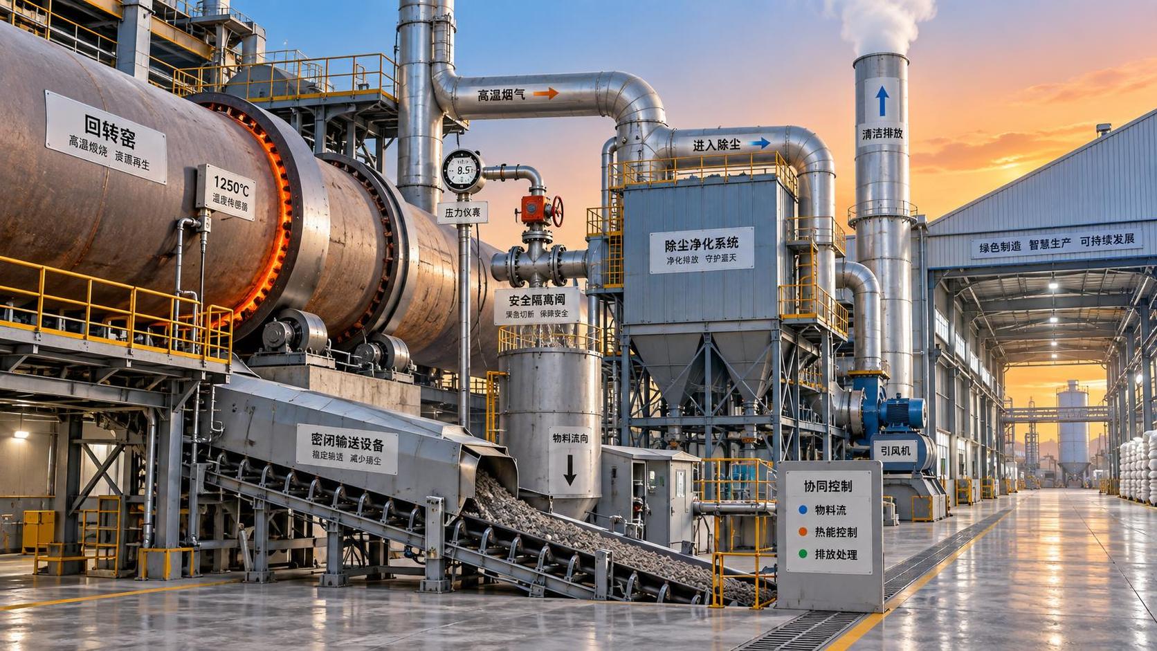
Many projects fail economically at the interface with the existing plant. A recovery package needs duct routing, foundations, access platforms, isolation dampers, bypasses, instrumentation, electrical works, civil modifications, and controls that coordinate with the main process. These items can be more decisive than the heat-recovery unit itself.
Ask where the equipment will sit during operation and maintenance. Can tube bundles, filters, fans, valves, or pumps be inspected and replaced without extended production disruption? Is there enough elevation and space for drainage, expansion, access, and safe lifting? Can the unit be isolated if it fouls or trips, allowing the kiln or furnace to continue operating through a protected bypass?
Pressure drop requires particular discipline. On exhaust systems, extra resistance can affect draft, fan power, combustion behaviour, and emissions-control performance. A supplier’s thermal proposal should therefore be reviewed with the plant’s gas-handling and control constraints, not treated as an isolated package calculation.
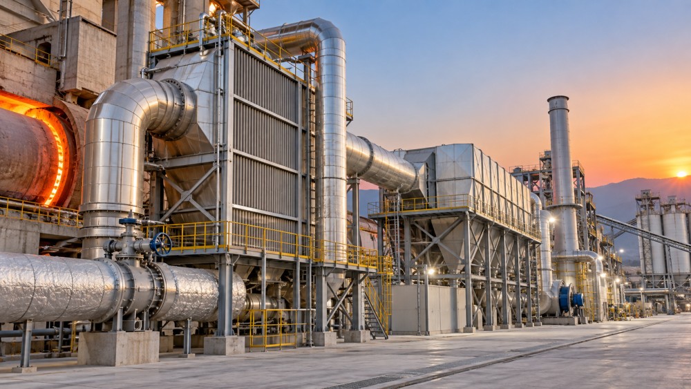
Materials, fouling, and corrosion determine lifecycle value
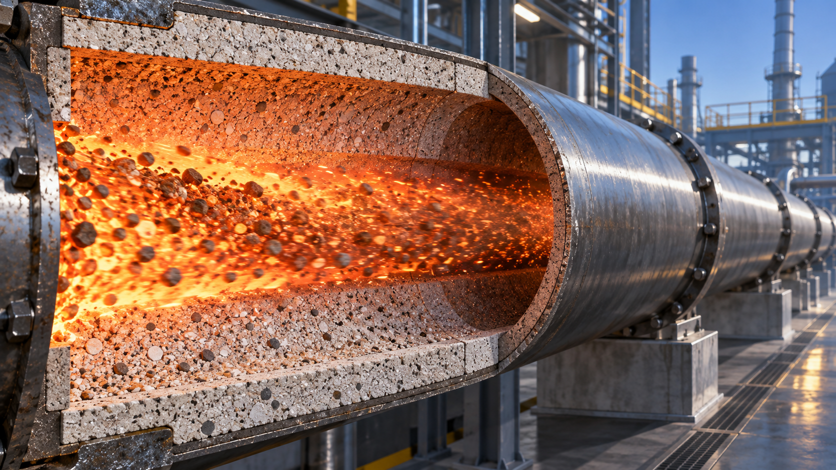
For high-temperature processes, the equipment that transfers heat is often exposed to the same conditions that make the process difficult: abrasive dust, thermal cycling, sticky deposits, corrosive species, and rapid shifts in gas temperature. The useful question is not simply which alloy is offered. It is whether the full design accounts for local metal temperatures, acid-dew-point risk, dust deposition patterns, erosion zones, cleaning access, and expected shutdown practices.
A compact exchanger may achieve high thermal recovery on paper but be inappropriate where particulate loading is high and cleaning cannot be performed online. A more conservative arrangement with wider passages, lower gas velocity, soot-blowing or mechanical cleaning provisions, and a manageable bypass can deliver better annual performance. In dirty-service applications, recoverable heat after months of operation matters more than clean-surface performance at commissioning.
Thermal expansion also deserves attention. Kiln and furnace lines move, cycle, and experience transients. Rigid ductwork or poorly arranged expansion joints can transfer loads into exchanger casings and connections. Review the mechanical design alongside the process design, especially where refractory-lined ducts, large fans, or hot-gas branches are involved.
Evaluate emissions and process risk as part of the same decision
Energy recovery equipment changes gas temperature, residence time, pressure conditions, and sometimes the sequence of downstream treatment. These changes can affect filters, scrubbers, selective reduction systems, induced-draft fans, stack behaviour, and continuous monitoring arrangements. The recovery system must support, rather than compromise, the plant’s environmental operating envelope.
Cooling a gas stream too early can create condensation and deposition problems. Removing too much heat before a downstream process may also reduce the temperature required for effective treatment or alter the conditions under which existing equipment was designed to operate. This is especially relevant for industrial incineration, alternative-fuel use, and processes with variable raw material chemistry.
The assessment should include credible upset conditions: loss of circulation, fan failure, power interruption, sudden gas-temperature rise, reduced heat demand, cold startup, and unplanned process stops. A useful design defines what happens in each case. Automatic bypasses, dump loads, controlled recirculation, isolation logic, and temperature protection are not optional details; they determine whether recovery equipment is a productivity asset or an additional source of trips.
Compare proposals on annual usable energy, not headline capacity
When comparing suppliers, place every proposal on the same basis. Nominal heat duty alone hides too much. Request a defined set of operating cases, including normal operation, low production rate, startup or transition periods where relevant, and fouled-condition assumptions. The proposal should show expected recovered energy, auxiliary electricity use, pressure drop, outlet conditions, availability assumptions, maintenance intervals, and the consequences of bypass operation.
Lifecycle comparison should also include items that are easy to leave outside a quotation: refractory work, duct modification, instrumentation, water treatment, cleaning systems, cooling infrastructure, spare parts, commissioning support, operator training, and the cost of lost output during installation. A lower initial price can be outweighed by recurrent cleaning, difficult access, high fan power, or an extended outage for a failure-prone component.
For European plants, the carbon case should be assessed in the same model as the energy case. Avoided fuel and avoided electricity have different operational and carbon implications, and the result depends on what the recovered energy actually replaces. A project should not be credited twice by counting the same recovered heat as both direct fuel displacement and electricity production.
A practical evaluation sequence
- Measure and validate the source. Use operating data that represents normal variability, not a single favourable test point.
- Rank possible heat users. Prefer nearby, stable demands that can accept the available temperature level.
- Screen recovery routes. Eliminate options that require unrealistic uptime, cooling, space, or utility connections.
- Conduct a dirty-service and transient review. Test assumptions about fouling, corrosion, cycling, bypassing, and maintenance access.
- Model plant integration. Include ducts, fans, controls, emissions equipment, shutdown scope, and process interlocks.
- Compare annual operating cases. Judge proposals by usable energy and availability over time, with auxiliary loads included.
- Set acceptance criteria before purchase. Define performance boundaries, test conditions, documentation, training, spares, and responsibilities at interfaces.
Where external process intelligence is useful
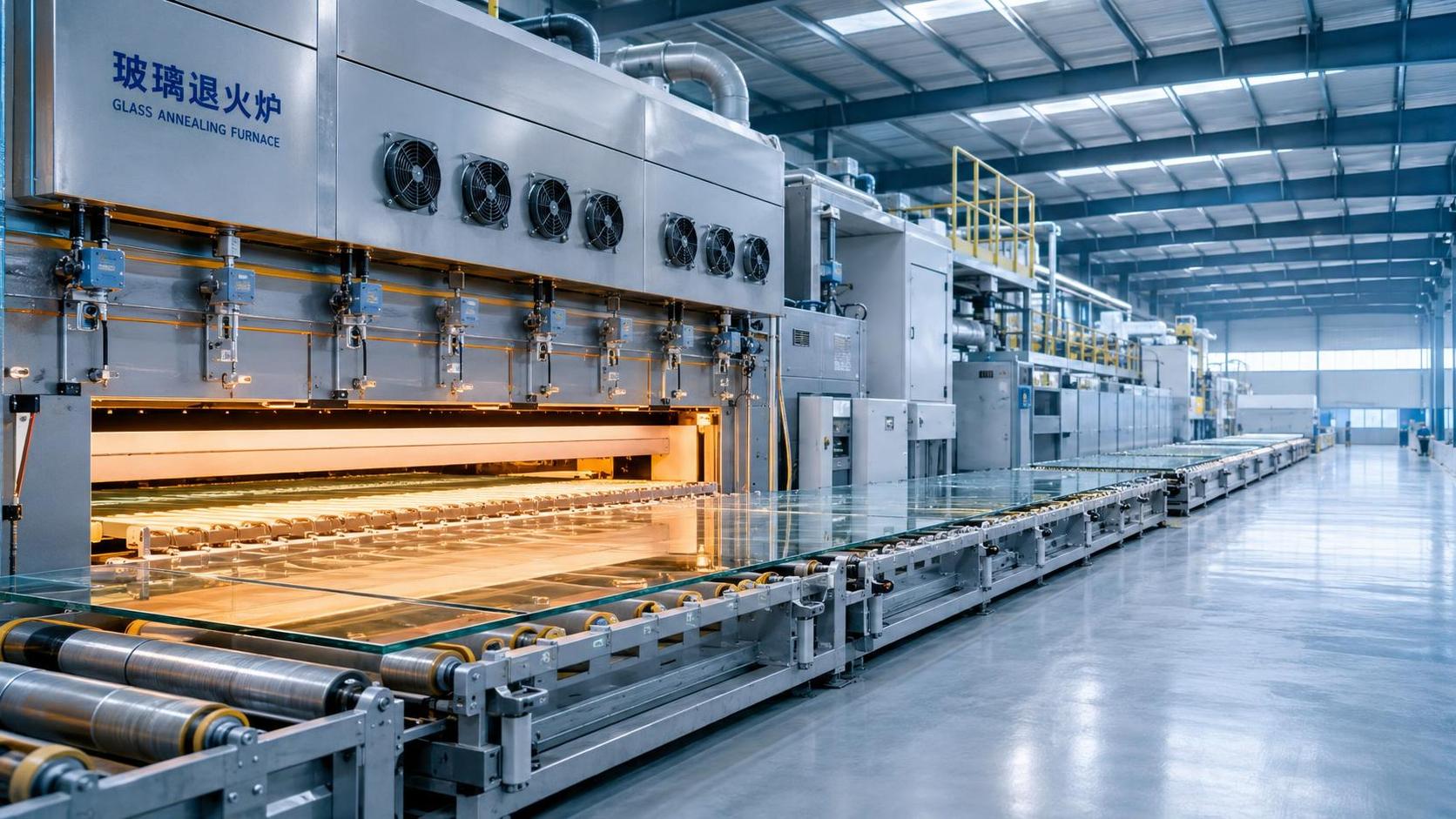
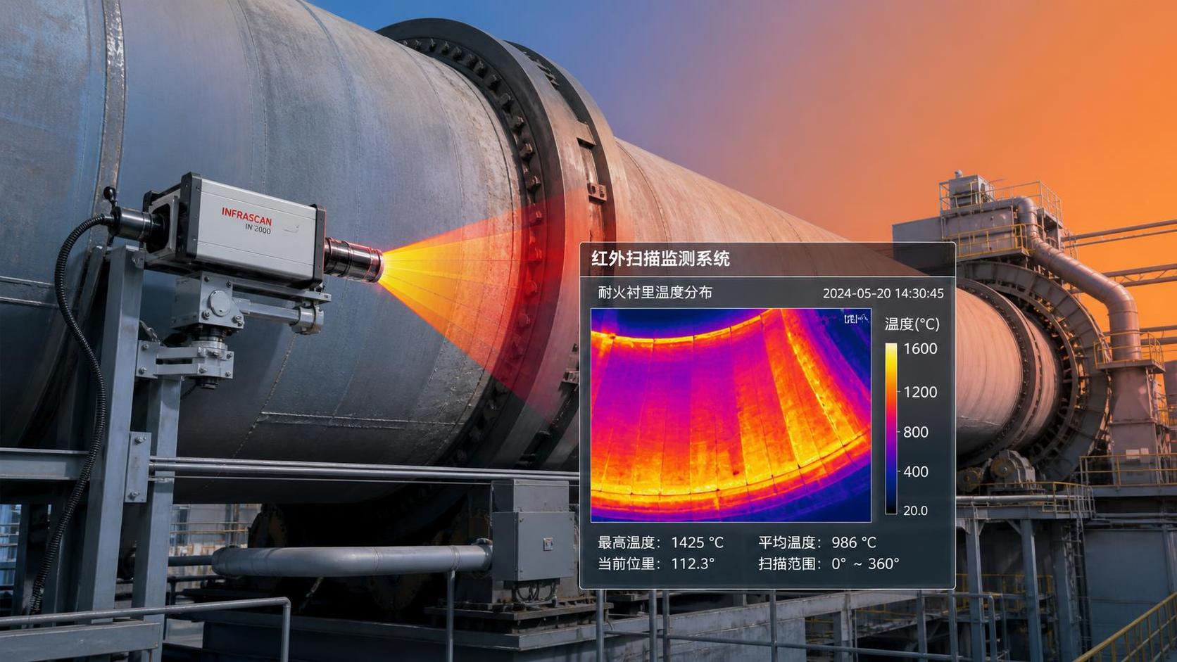
Some assessments require more than equipment specifications because the answer sits between thermal design, material behaviour, process chemistry, and regional operating conditions. This is common in cement, glass, refractory production, waste-to-energy, and extrusion-linked drying lines. Technical intelligence resources such as CF-Elite can be useful for framing these cross-disciplinary questions, particularly when evaluating kiln co-processing, refractory-lining monitoring, glass-line thermal behaviour, or wider decarbonisation pathways.
The decision should still be grounded in site-specific measurements and an integrated process review. A recovery system is not successful because it extracts the maximum possible heat at one location. It succeeds when it produces useful energy consistently, protects the core process, remains serviceable in the plant’s actual gas conditions, and continues to make sense as operating patterns change.
Related News
 Thermal Energy ArchitectHow European Plants Can Evaluate Energy Recovery Equipment for High-Temperature ProcessesIndustrial energy recovery equipment Europe: learn how high-temperature plants can assess waste-heat sources, integration risks, lifecycle value, and reliable recovery routes.Sep 20, 2026
 Thermal Energy ArchitectIndustrial Furnace Process Optimization: Reducing Fuel Use Without Sacrificing ThroughputIndustrial process optimization furnace strategies that cut fuel use while protecting throughput. Explore combustion control, heat recovery, refractory performance, and data-driven efficiency gains.Sep 19, 2026
 Ms. Elena RodriguezWhat Drives High-Pressure Extrusion Equipment Cost in Industrial Projects?High pressure extrusion equipment cost explained: compare pressure, die design, automation, wear, energy, and installation factors for smarter industrial investments.Sep 18, 2026
 Thermal Energy ArchitectHow to Size a Waste Heat Recovery Exchanger for High-Temperature Kiln Exhaust?Waste heat recovery exchanger sizing for high-temperature kiln exhaust: balance recoverable duty, fouling, corrosion limits, pressure drop, and reliable heat use.Sep 17, 2026
 Thermal Energy ArchitectWhy Heat-Resistant Materials Lose Abrasion Resistance at High TemperaturesHeat-resistant materials abrasion resistance can decline at high temperatures. Discover the thermal, chemical, and mechanical causes of wear—and how to choose longer-lasting linings.Sep 16, 2026
 Thermal Energy ArchitectHow to Evaluate a Thermal Energy Optimization Company for High-Temperature PlantsChoose a thermal energy optimization company with proven process expertise, measurable savings, and reliable delivery for high-temperature plants. Learn what to assess.Sep 15, 2026
 Thermal Energy ArchitectRotary Kiln Efficiency: How Feed Rate, Fuel Use, and Heat Loss Affect OutputRotary kiln efficiency explained: discover how feed rate, fuel use, heat loss, combustion, and cooling performance shape output, quality, and energy costs.Sep 14, 2026
 Thermal Energy ArchitectHow to Select Heat-Resistant Materials That Maintain Abrasion Resistance in KilnsHeat-resistant materials abrasion resistance: learn how to select kiln linings that withstand heat, wear, thermal cycling, and chemical attack for longer service life.Sep 13, 2026
 Thermal Energy ArchitectHow Rotary Kiln Automation Improves Temperature Control and Fuel EfficiencyRotary kiln technology automation enhances temperature control, stabilizes combustion, and improves fuel efficiency with smarter data, predictive control, and safer operations.Sep 12, 2026
 Silicate Process EngineerCement Plant Emission Control: Selecting Systems for Dust, NOx, and SO2 LimitsCement plant emission control guide: compare dust collectors, NOx reduction, and SO2 systems for reliable compliance across kiln modes, fuel changes, and operating upsets.Sep 11, 2026
 Thermal Energy ArchitectSelecting Abrasion-Resistant High-Temperature Materials for Kiln and Conveyor Wear ZonesHigh-temp material engineering guide to abrasion-resistant kiln and conveyor solutions—match wear, heat, chemistry, and installation design for longer service life.Sep 10, 2026
 Dr. Alistair VaughnIndustrial Process Engineering: How to Map Processes for Safer, More Efficient PlantsIndustrial process engineering reveals bottlenecks, safety risks, and energy losses through practical process mapping for safer, more efficient plants.Sep 09, 2026
 Optical Glass Tech FellowHow to Evaluate a Glass Annealing Equipment Manufacturer for Production StabilityChoose a glass annealing equipment manufacturer with proven thermal uniformity, reliable controls, lifecycle value, and responsive service for stable production.Sep 08, 2026
 Prof. Marcus ChenThermal Energy Architecture in North America: Strategies for Lower Building Energy UseThermal energy architecture North America helps project leaders cut building energy use through stronger envelopes, right-sized HVAC, storage, and smart commissioning.Sep 07, 2026
 Ms. Elena RodriguezHow Should Buyers Evaluate Building Material Industry Intelligence Pricing?Building material industry intelligence pricing: learn how to compare coverage, technical depth, and ROI to choose intelligence that reduces procurement risk.Sep 07, 2026
 Ms. Elena RodriguezHow to Use Building Material Intelligence Data for Market and Investment DecisionsBuilding material industry intelligence data helps leaders evaluate demand, costs, regulation, capacity, and technology to make smarter market and investment decisions.Sep 05, 2026
 Thermal Energy ArchitectHow PLC Control Improves Energy Efficiency and Temperature Stability in KilnsEnergy efficient kilns PLC control improves temperature stability, cuts fuel waste, and optimizes combustion, draft, and material flow. Explore proven strategies for smarter kiln modernization.Sep 04, 2026
 Optical Glass Tech FellowEuropean Glass Melting Processes: Furnace Choices, Energy Use, and Quality ControlGlass melting process Europe: explore furnace choices, energy efficiency, cullet strategy, and quality control to improve output, compliance, and long-term glass performance.Sep 03, 2026
 Thermal Energy ArchitectWhat Determines Refractory Lining Monitoring Price for Industrial Kilns?Refractory lining monitoring price depends on kiln size, sensor technology, installation, software, and support. Compare total lifecycle costs and choose the right solution.Sep 02, 2026
 Silicate Process EngineerCement Production System Costs: A Plant Buyer’s Guide to Budgeting and ROICement production systems cost planning made clear: compare CAPEX, operating costs, compliance, and ROI to build a resilient, profitable cement plant investment.Sep 01, 2026



Related News
- 00
0000-00
How European Plants Can Evaluate Energy Recovery Equipment for High-Temperature Processes - 00
0000-00
Industrial Furnace Process Optimization: Reducing Fuel Use Without Sacrificing Throughput - 00
0000-00
How to Size a Waste Heat Recovery Exchanger for High-Temperature Kiln Exhaust? - 00
0000-00
Why Heat-Resistant Materials Lose Abrasion Resistance at High Temperatures - 00
0000-00
How to Evaluate a Thermal Energy Optimization Company for High-Temperature Plants
Weekly Insights
Stay ahead with our curated technology reports delivered every Monday.