
Silicate Processing Equipment Production Line: Key Machines, Layout Options, and Output Planning




Silicate Processing Equipment Production Line: Key Machines, Layout Options, and Output Planning
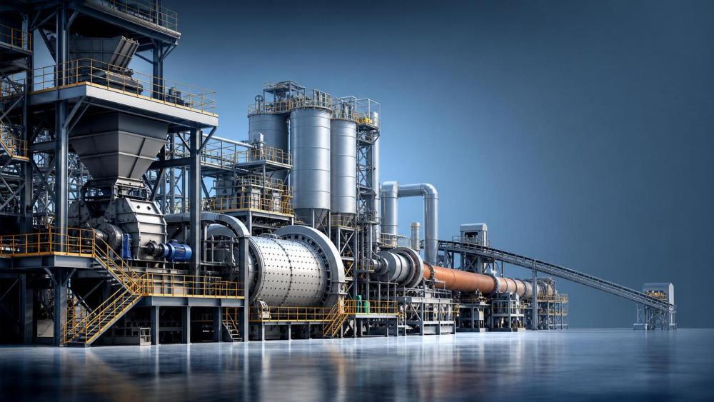
Planning a silicate processing equipment production line starts with process logic, not isolated machine selection.
A workable line must balance raw material behavior, thermal load, capacity targets, and plant expansion limits.
That is why early engineering choices often shape operating cost more than later procurement negotiation.
In practical terms, a silicate processing equipment production line usually covers crushing, grinding, mixing, calcining, cooling, conveying, storage, and control.
The exact combination depends on feed chemistry, moisture, particle size, product grade, and emissions requirements.
For large projects, layout and output planning matter just as much as equipment quality.
A line that looks complete on paper can still underperform if material flow creates bottlenecks or unstable kiln loading.
This guide breaks down the key machines, common layout models, and realistic output planning rules behind a dependable silicate processing equipment production line.
Core Machines in a Silicate Processing Equipment Production Line
Most projects begin with raw material preparation.
If the feed includes lump minerals, clay, feldspar, or quartz-rich components, primary crushing is the first duty.
Jaw crushers handle larger feed sizes well.
Hammer or impact crushers suit softer or more friable silicate materials.
After that, grinding equipment defines downstream stability.
Ball mills remain common for broad applications and variable materials.
Vertical roller mills can reduce power use and simplify drying when feed moisture is inconsistent.
High-efficiency classifiers are equally important because product fineness directly affects reaction speed and final quality.
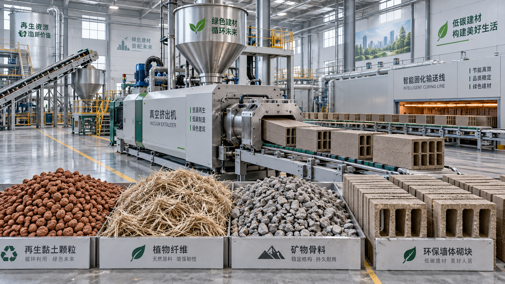
The next block is batching and mixing.
This stage often includes dosing bins, weigh feeders, belt scales, mixers, and homogenization silos.
Poor proportioning here will usually show up later as unstable firing temperature, variable strength, or off-spec chemistry.
- Crushing equipment controls feed size consistency.
- Grinding systems control particle distribution and reaction efficiency.
- Dosing and mixing systems protect formula accuracy.
- Storage and reclaim systems stabilize line continuity.
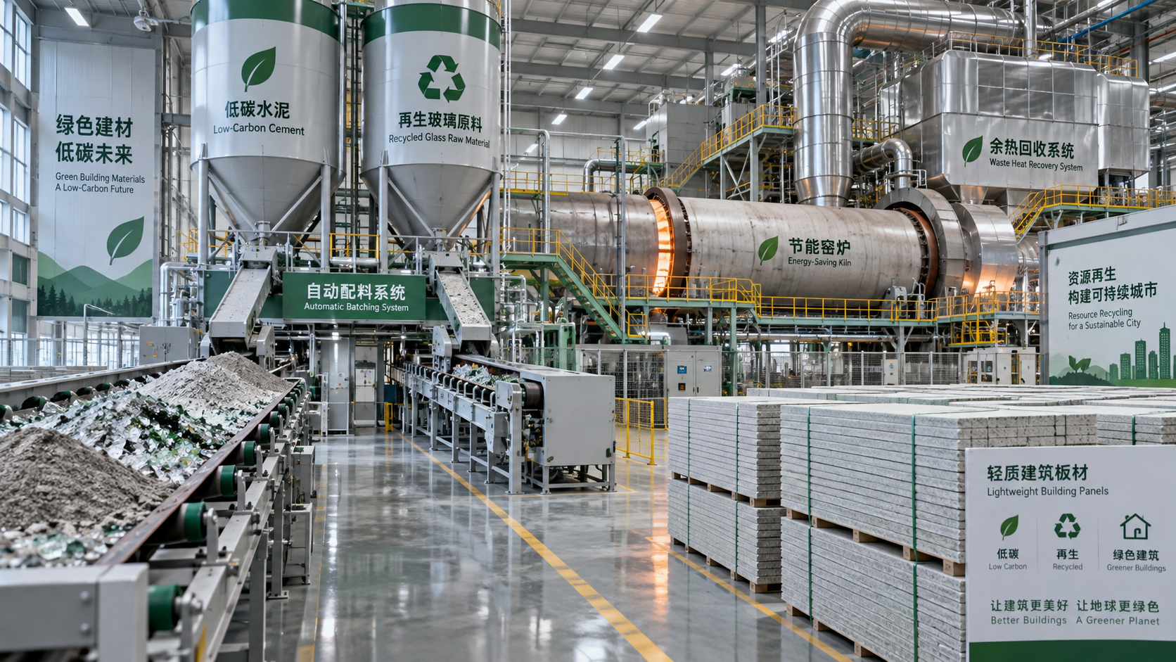
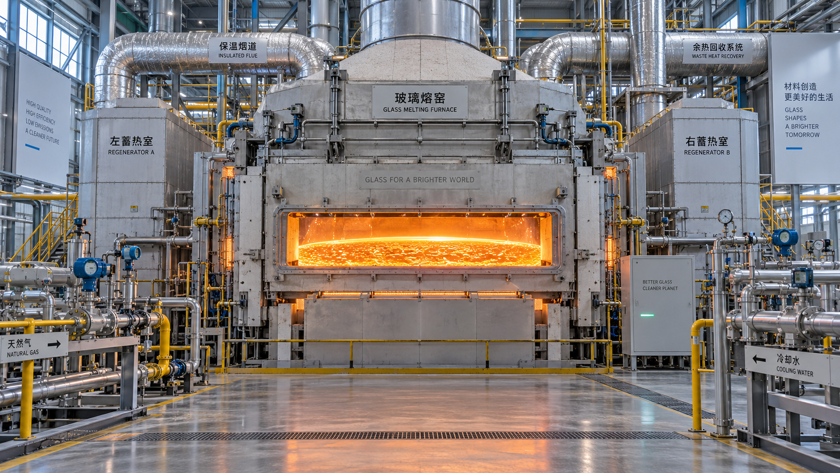
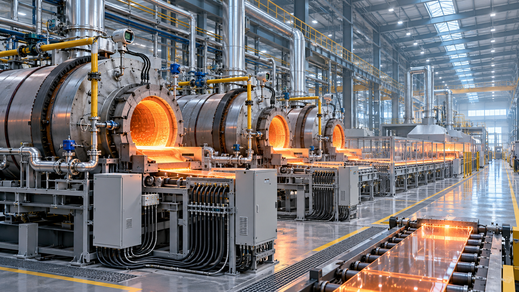
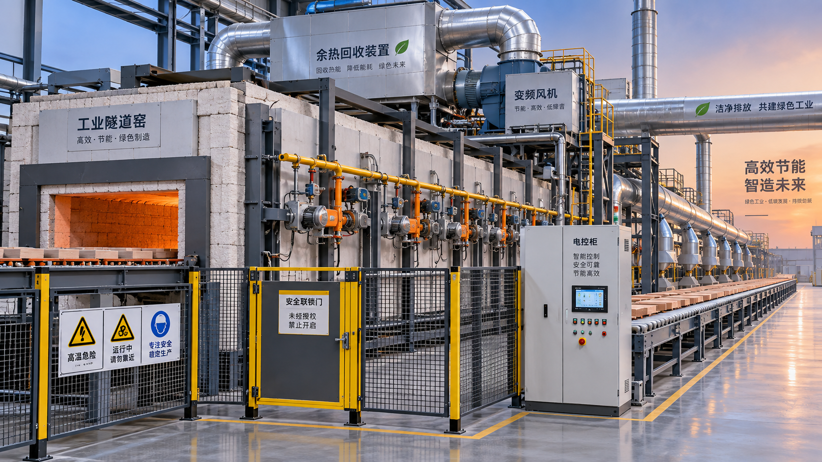
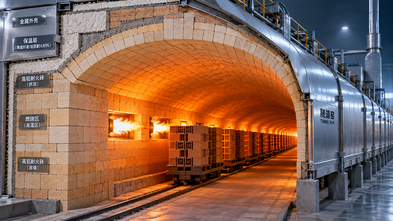
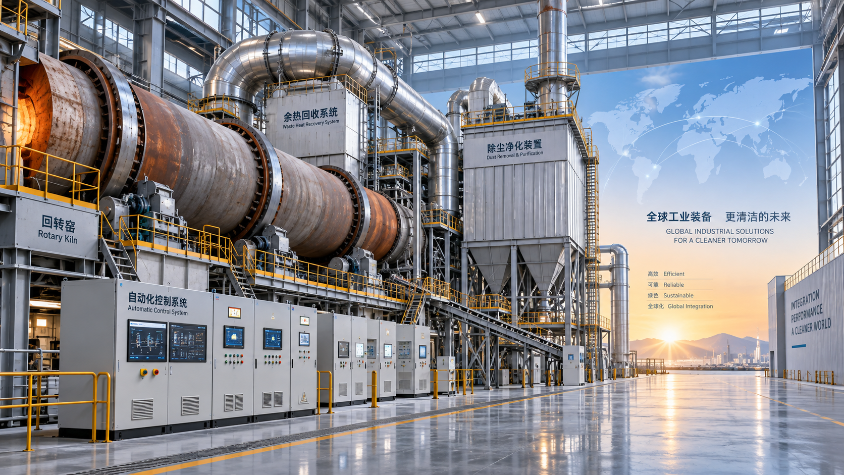
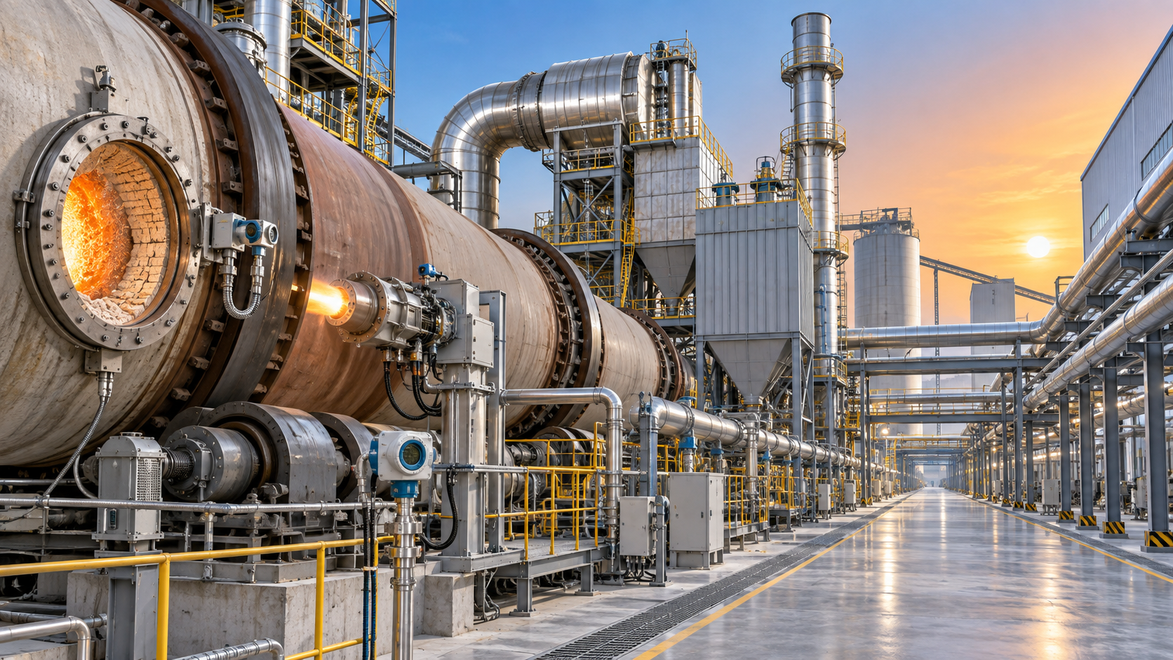
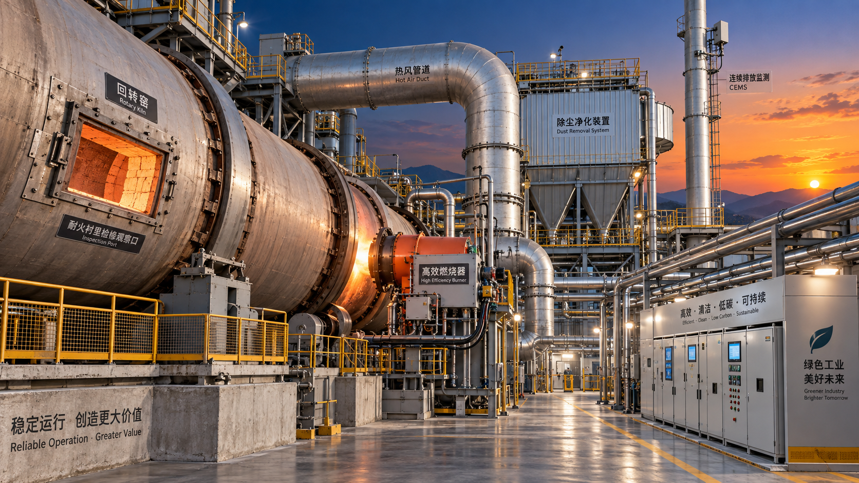
The thermal section is often the cost center and the technical heart of the silicate processing equipment production line.
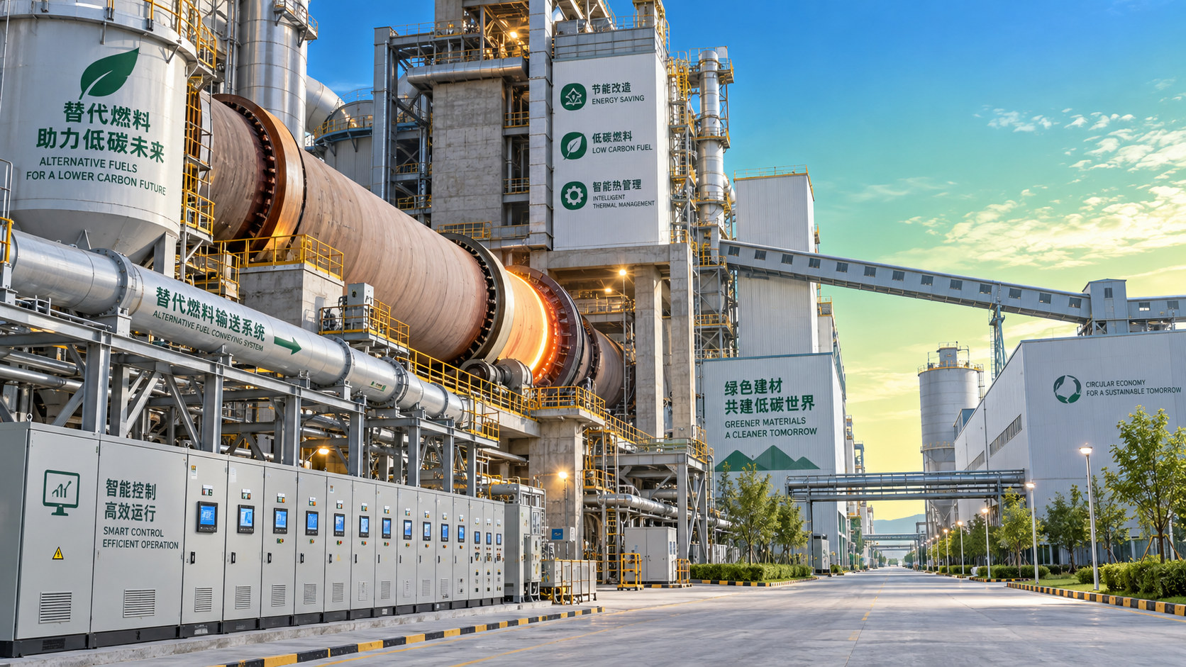
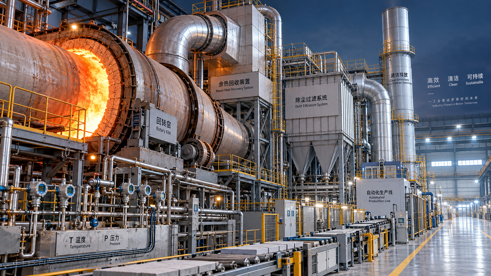
Depending on product type, this may use a rotary kiln, shaft kiln, tunnel kiln, or fluidized thermal unit.
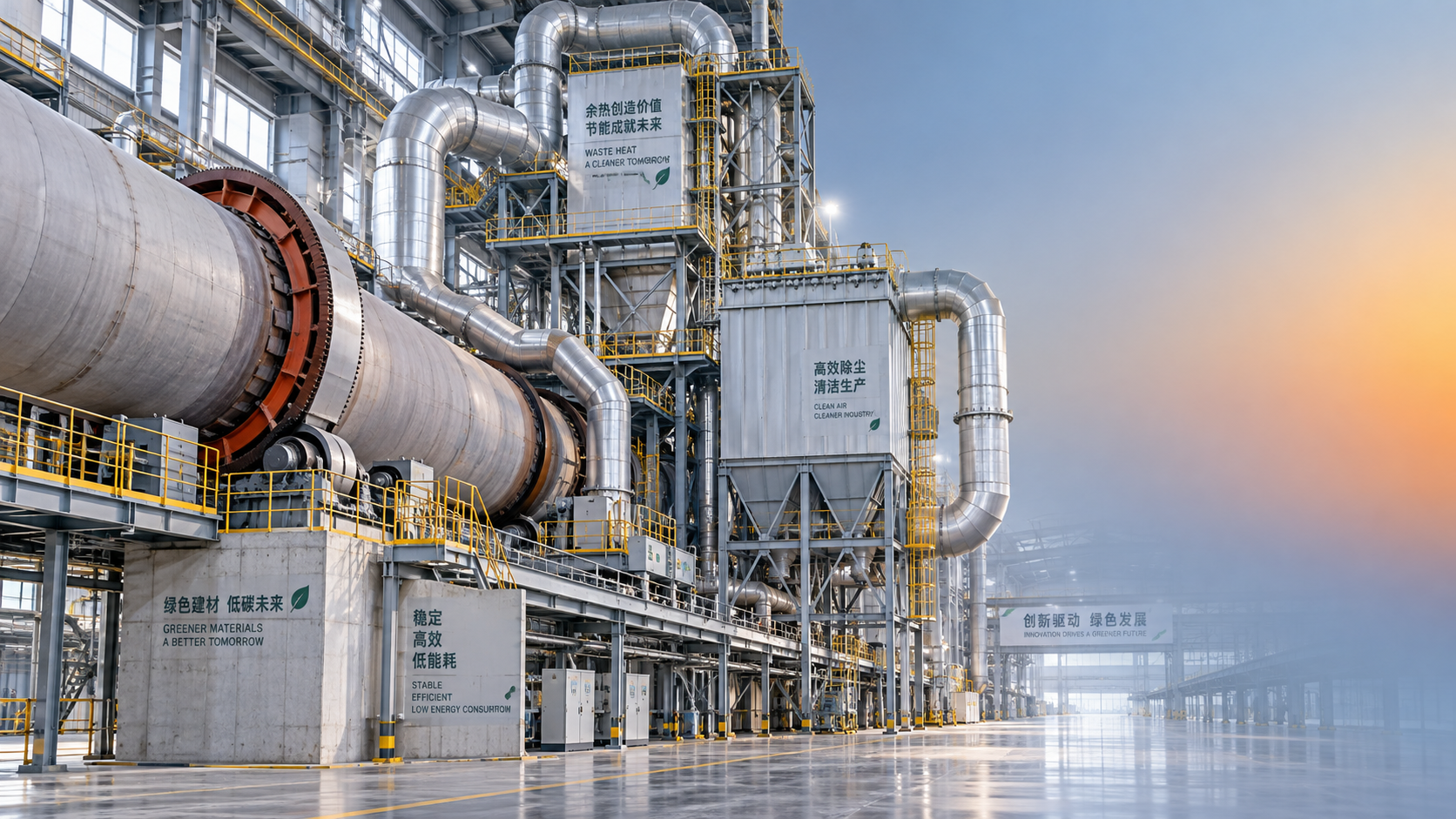
Rotary kilns are favored where reaction uniformity, fuel flexibility, and high throughput matter.
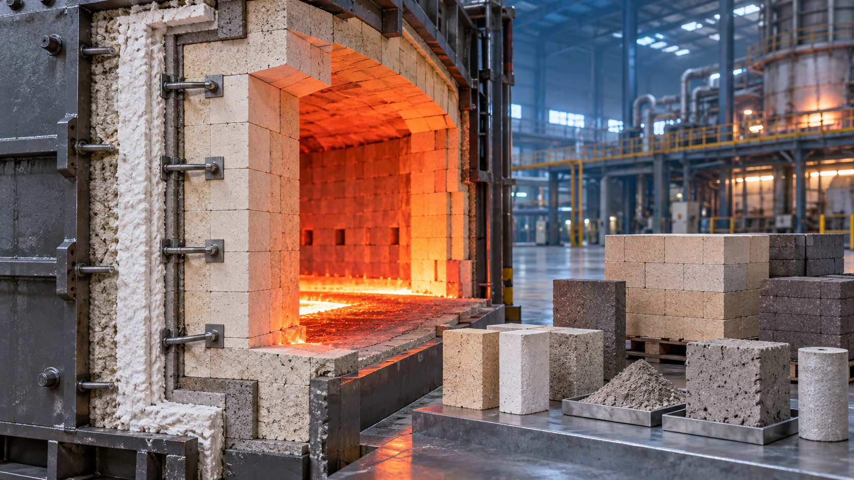
Supporting equipment includes burners, draft fans, preheaters, refractory lining, temperature instruments, and off-gas treatment units.
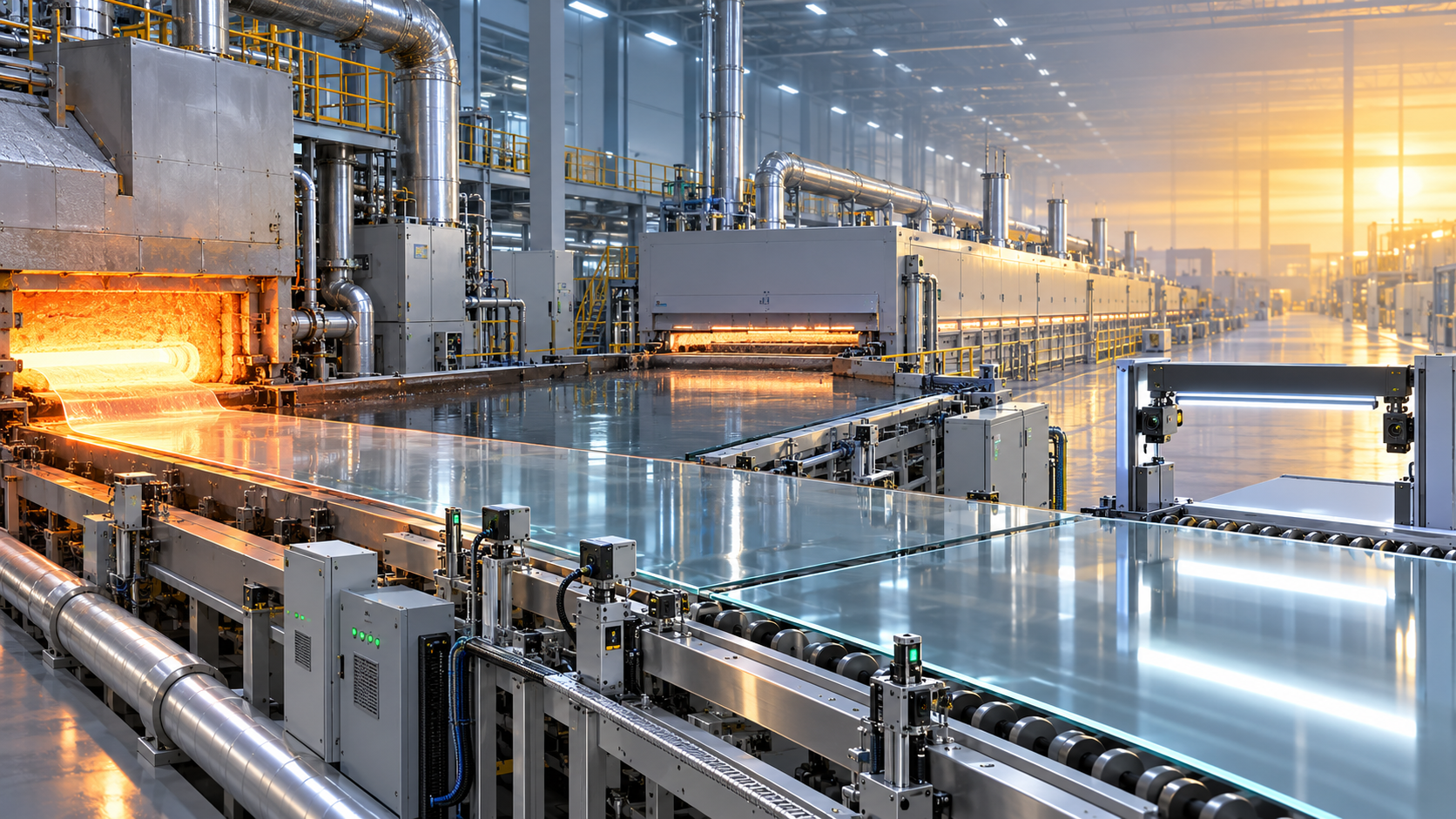
After calcining or firing, cooling equipment protects product quality and heat recovery potential.
Then conveying, screening, storage, and packing complete the line.
How Process Flow Shapes Layout Decisions
A silicate processing equipment production line should be laid out around material movement, maintenance access, and thermal integration.
When layout is treated as a late drawing task, transport distances and transfer points usually multiply.
That raises dust loss, power demand, and downtime risk.
In greenfield projects, linear layouts are common.
They are easy to understand, simpler to phase, and suitable for long plots.
However, they may create longer conveyor runs and weaker heat integration.
Compact block layouts reduce transfer distance and often improve operator supervision.
They work well where land cost is high or site boundaries are tight.
The tradeoff is tighter maintenance space and more demanding installation sequencing.
Vertical layouts can also make sense when gravity flow reduces handling steps.
This is especially useful for raw meal bins, dosing towers, and some grinding circuits.
Still, taller structures can raise civil cost and slow maintenance response.
Three Practical Layout Models
- Linear flow model for simple logistics and staged expansion.
- Compact cluster model for shorter transport paths and lower dust escape.
- Hybrid vertical model for gravity-assisted handling and tighter process control.
The right option depends on site geometry, utility corridors, environmental permits, and future debottleneck plans.
A strong silicate processing equipment production line layout also separates hot zones, dusty zones, and maintenance routes clearly.
That improves safety and makes shutdown planning far easier.
Output Planning: Matching Capacity Across the Line
Capacity planning is where many silicate projects become too optimistic.
Nameplate ratings do not equal stable production.
A silicate processing equipment production line performs at the pace of its real bottleneck.
That bottleneck is often the grinder, dryer, kiln, cooler, or packaging station.
Start with annual output demand, then convert it into daily and hourly net production.
After that, correct for maintenance shutdowns, start-stop losses, moisture variation, and quality rejection rates.
This usually changes equipment sizing assumptions more than expected.
A more reliable method is to size each section with a practical buffer, not a theoretical peak.
For example, conveyors and bins should absorb short disturbances without forcing kiln instability.
Likewise, the firing section should match upstream consistency before chasing maximum tonnage.
In real operations, a slightly lower design speed often delivers a higher annual output.
Energy, Emissions, and Control Systems
A modern silicate processing equipment production line is judged by more than throughput.
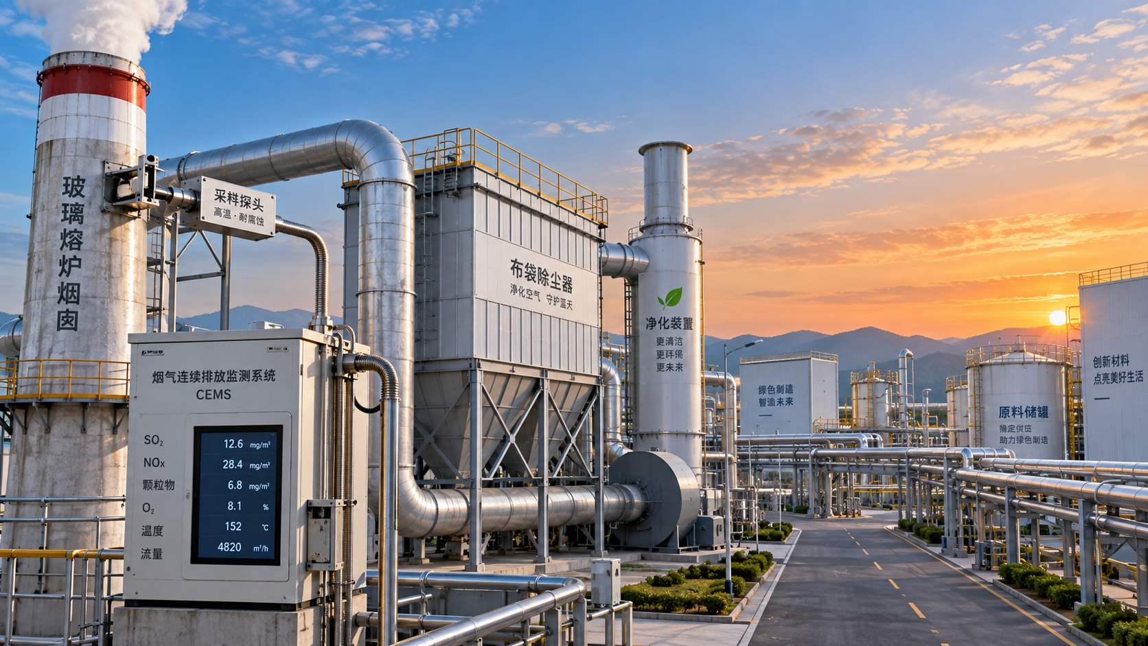
Fuel efficiency, dust control, heat recovery, and process visibility now drive investment decisions.
This is becoming more visible as environmental regulation tightens across heavy material industries.
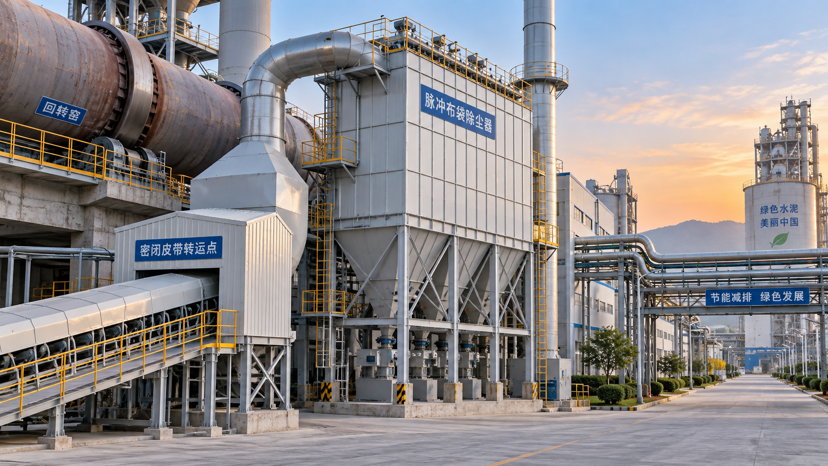
Bag filters, cyclones, desulfurization units, and NOx control systems should be planned with process variability in mind.
If the gas system is undersized, the whole line can lose stability.
Control architecture matters too.
A basic PLC setup may be enough for smaller lines.
For larger installations, DCS integration, historian data, online analyzers, and predictive maintenance tools offer clearer value.
The stronger signal in recent projects is that digital monitoring is moving from optional to standard.
Operators want earlier warnings on refractory wear, burner drift, fan imbalance, and product variability.
That also means the silicate processing equipment production line should reserve instrument access, cable routing, and panel space from day one.
Key Risks During Line Design and Procurement
Several design errors appear repeatedly in silicate line projects.
- Sizing the kiln for target output while ignoring upstream fineness instability.
- Choosing machines by isolated capacity rather than integrated process balance.
- Reducing buffer storage to save capital, then losing continuity in operation.
- Leaving little space for maintenance cranes, refractory work, or bag filter access.
- Underestimating utility demand for air, water, fuel, and electrical redundancy.
Procurement should therefore be tied to validated process data.
Material testing, heat balance checks, and supplier interface reviews are worth the time.
This is especially true when fuels vary, recycled materials are introduced, or product grades may change later.
A flexible silicate processing equipment production line usually costs less over its service life than a narrowly optimized one.
A Practical Planning Path for Better Project Outcomes
A strong project usually follows a disciplined sequence.
- Define product specification, annual output, and raw material envelope.
- Map the process route and identify likely bottlenecks early.
- Compare layout options against land, utilities, and expansion goals.
- Build a realistic heat and mass balance for the full line.
- Select core equipment around stable operating range, not only peak rating.
- Reserve space for emissions systems, maintenance, and digital instrumentation.
- Validate supplier interfaces before final procurement release.
That sequence keeps the silicate processing equipment production line aligned with technical reality and long-term operating economics.
It also reduces the common gap between designed output and delivered output.
For teams shaping new plants or line upgrades, the main takeaway is straightforward.
Treat the silicate processing equipment production line as one connected system.
When machines, layout, control, and output planning are matched early, the project becomes easier to run, scale, and improve.
Related News
 Ms. Elena RodriguezHigh-Pressure Molding Innovations: How Automation and Tooling Affect PriceExplore the high-pressure molding innovations price equation: compare automation, tooling, and ownership costs to find upgrades that cut waste and deliver measurable value.Oct 13, 2026
 Ms. Elena RodriguezIndustrial Process Optimization: Where to Target Energy, Yield, and Throughput LossesIndustrial process optimization: identify energy, yield, and throughput losses to improve plant stability, reduce costs, and unlock measurable performance gains.Oct 12, 2026
 Ms. Elena RodriguezGlass Market Intelligence: How to Assess Demand, Capacity, and Regional Growth RisksGlass market intelligence for evaluating demand, effective capacity, energy exposure, trade dynamics, and regional growth risks before investing in glass manufacturing.Oct 11, 2026
 Ms. Elena RodriguezAre Green Building Materials More Expensive to Manufacture?Are green building materials more expensive to manufacture? Explore cost drivers, savings opportunities, and how sustainable production can strengthen long-term competitiveness.Oct 13, 2026
 Structural Material AnalystWhich Sustainable Construction Materials Are Suitable for Extrusion?Which sustainable construction materials are suitable for extrusion? Explore recycled clay, cementitious mixes, geopolymers, and bio-composites for reliable, lower-impact building products.Oct 12, 2026
 Optical Glass Tech FellowWhat Should a Glass Furnace Energy Specification Include?What should be included in a glass furnace energy specification? Explore performance, fuel flexibility, heat recovery, emissions, and monitoring essentials.Oct 11, 2026
 Dr. Alistair VaughnHow Process Technology Platforms Improve Control Across Multi-Line ManufacturingDiscover how a process technology platform strengthens cross-line control, connects operational data, and improves energy, quality, and maintenance decisions.Oct 10, 2026
 Optical Glass Tech FellowHow Glass Furnace Emissions Are Measured and Controlled for Regulatory ComplianceGlass furnace emissions: learn how to measure, monitor, and control NOx, SOx, particulate, CO, and CO2 for reliable regulatory compliance.Oct 08, 2026
 Prof. Marcus ChenIndustrial Decarbonization Strategies in Europe: A Roadmap for Energy-Intensive PlantsIndustrial decarbonization strategies Europe: explore practical pathways for energy-intensive plants to cut emissions, improve efficiency, and protect performance.Oct 07, 2026
 Thermal Energy ArchitectEnergy-Efficient Silicate Production Lines: What to Compare Before SelectionSilicate production lines energy efficient selection guide: compare thermal performance, stability, emissions, controls, and lifecycle value before investing.Oct 06, 2026
 Optical Glass Tech FellowHow to Evaluate Automated Float Glass Lines for Capacity, Quality, and Energy UseEvaluate automated float glass lines for net capacity, consistent quality, energy efficiency, automation reliability, and lifecycle value. Explore key criteria for smarter investment decisions.Oct 05, 2026
 Thermal Energy ArchitectWhat Does CE Marking Require for an Energy-Efficient Industrial Kiln?Energy efficient kiln CE requirements explained: assess safety, technical files, energy performance, and EU compliance before purchase or commissioning.Oct 04, 2026
 Thermal Energy ArchitectRefractory Manufacturing Solutions for Brick Plants: How to Extend Kiln LifeRefractory manufacturing solutions for brick plant operations: discover proven strategies to extend kiln life, reduce heat loss, prevent lining failures, and plan cost-effective repairs.Oct 03, 2026
 Thermal Energy ArchitectHow to Specify Heavy Industrial Process Systems for High-Temperature PlantsHeavy industrial processes systems: learn how to specify high-temperature plants for efficiency, emissions control, maintainability, and lifecycle performance.Oct 02, 2026
 Structural Material AnalystHow Sustainable Material Extrusion Can Improve Wall Panel Durability and Design FlexibilityDiscover how sustainable material extrusion for wall panels improves durability, moisture resistance, design flexibility, and installation consistency for high-performing wall systems.Oct 01, 2026
 Thermal Energy ArchitectHow to Evaluate a High-Temperature Materials Manufacturer for Furnace ApplicationsChoose a high-temperature materials manufacturer with confidence: compare thermal performance, chemical resistance, quality controls, installation support, and lifecycle cost.Sep 30, 2026
 Ms. Elena RodriguezHow to Structure Global Specification Data for Faster Industrial Product EvaluationGlobal specification-oriented product information helps industrial teams compare capacity, energy, emissions, automation, and lifecycle data on a like-for-like basis for faster, confident equipment decisions.Sep 29, 2026
 Thermal Energy ArchitectHow to Specify High-Temperature Process Systems for Continuous Thermal OperationsHigh-temperature process engineering systems: learn how to specify resilient continuous thermal operations for efficiency, compliance, reliable uptime, and long-term performance.Sep 28, 2026
 Thermal Energy ArchitectHow to Evaluate a Thermal Engineering Contractor for High-Temperature Plant ProjectsChoose a thermal engineering contractor with proven process expertise, lifecycle value, emissions control, and delivery discipline for reliable high-temperature plant performance.Sep 27, 2026
 Silicate Process EngineerHow Latin American Cement Plants Can Reduce Dust Emissions in Kilns and Transfer PointsCement plant dust control Latin America: reduce kiln and transfer-point emissions with practical airflow, filtration, monitoring, and maintenance strategies.Sep 26, 2026

Related News
- 00
0000-00
How Process Technology Platforms Improve Control Across Multi-Line Manufacturing - 00
0000-00
How Waste Recycling Technology Improves Material Recovery in Industrial Plants - 00
0000-00
Industrial Process Engineering: How to Map Processes for Safer, More Efficient Plants - 00
0000-00
What Should a Process Technology Database Track for High-Temperature Plants? - 00
0000-00
How to Specify Custom Agricultural Processing Equipment for Throughput and Hygiene
Weekly Insights
Stay ahead with our curated technology reports delivered every Monday.