
How to Size High Pressure Molding Equipment Tonnage for Part Geometry and Cycle Time




Selecting the right high pressure molding equipment tonnage is primarily a sizing problem, not a catalog problem. Technical evaluators usually need to know whether a proposed machine can hold the mold closed, fill the geometry consistently, and still meet the required cycle time without wasting energy or overspending on capacity.
In practice, the correct tonnage comes from balancing projected clamping force, part shape complexity, cavity layout, material behavior, and throughput targets. If one of these inputs is treated in isolation, the equipment may look adequate on paper while creating instability, flash, slow cycles, or poor overall equipment efficiency in production.
Why Technical Evaluators Focus on Tonnage, Geometry, and Throughput Together
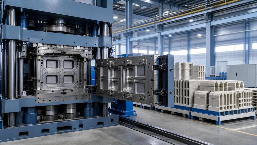
The core search intent behind high pressure molding equipment tonnage is clear: readers want a reliable way to size machinery for real production conditions, not just theoretical mold area. They are looking for a decision method that reduces technical risk before procurement or line expansion.
For technical evaluation teams, the main concern is usually not the maximum tonnage label itself. The real concern is whether the machine can maintain forming stability across the full cycle while handling the actual part geometry, pressure profile, and production rhythm required by the project.
This matters even more in industrial applications linked to building materials, refractory components, and specialized extrusion-related forming. In these sectors, geometry often includes ribs, thin walls, variable thickness zones, and large projected surfaces that increase force demand and make cycle timing less forgiving.
As a result, the best sizing approach starts with a practical question: what clamping force and motion performance are needed to produce this part repeatedly at the target output rate? Once that is answered, tonnage becomes one element of a broader machine-fit decision.
Start with Projected Area, but Do Not Stop There
The first input in sizing high pressure molding equipment tonnage is projected area. This is the area of the part, runner system, and cavities as seen from the mold opening direction. It is the baseline factor used to estimate the clamp force needed to resist cavity pressure.
Many evaluation errors begin when teams only compare machine tonnage to part weight or external dimensions. Neither of those alone is enough. A light part with a broad projected area can need more clamp force than a heavier part with compact geometry.
The basic relationship is straightforward: required clamp force is approximately projected area multiplied by cavity pressure, then adjusted by a safety factor. That sounds simple, but each term requires disciplined interpretation if the estimate is to be useful for procurement decisions.
Projected area must include all active cavity surfaces contributing to mold opening force. If the layout includes multiple cavities, runner spread, or a family mold arrangement, the total effective area can rise quickly and change the tonnage class under consideration.
For technical evaluators, this is the first checkpoint. If the area model is incomplete, every downstream judgment about machine size, cycle feasibility, and energy use will be distorted. A careful projected area calculation is therefore necessary, but it is only the beginning.
How Part Geometry Changes the Real Tonnage Requirement
Part geometry influences pressure distribution, venting behavior, fill resistance, and mold separation tendency. That means two molds with the same projected area may still require different practical tonnage windows because their shapes create very different forming loads during filling and packing.
Large flat sections tend to push clamp demand upward because pressure acts across a broad area and can promote flash at the parting line. Deep ribs, abrupt thickness transitions, and thin sections may require higher injection or molding pressure, which also increases the effective clamping requirement.
Complex geometry also raises sensitivity to deflection. Even if nominal tonnage looks sufficient, platen rigidity, tie-bar spacing, and mold support conditions can affect whether force is distributed evenly enough to protect dimensional consistency and avoid localized flashing.
Technical evaluators should therefore examine not only total area, but also geometry concentration. Ask where pressure peaks are likely to occur, where the parting line is vulnerable, and whether the mold base and machine support structure can maintain parallelism under load.
This is especially important for large-format molded construction materials or specialized thermal-resistant components. These products often combine wide faces with engineered internal features, creating a force profile that punishes undersized or mechanically imbalanced equipment.
Cavity Layout Can Shift the Equipment Class
Cavity count is often treated as a productivity choice, but it is equally a tonnage choice. Adding cavities expands total projected area, alters flow balance, increases material demand per shot, and may extend the time required for filling, cooling, and mold movement.
In early project reviews, teams sometimes assume that doubling cavity count simply doubles output. In reality, the machine may need a much larger clamp unit, greater shot capacity, stronger hydraulic or servo performance, and better thermal control to keep cycle time from slipping.
The layout itself also matters. A well-balanced cavity arrangement can distribute force more evenly across the platens, while an asymmetrical layout may produce uneven loading that reduces process stability even when the machine has enough nominal tonnage.
For this reason, cavity layout should be reviewed together with tie-bar spacing, platen dimensions, and mold footprint. A machine can meet the tonnage requirement on paper and still be a poor fit if the mold sits awkwardly within the clamp envelope or creates off-center loading.
When technical evaluators compare machine options, they should treat cavity strategy as part of the equipment sizing exercise. The most economical answer is not always the highest cavity count, especially when added complexity forces the project into a significantly larger machine platform.
Cycle Time Targets Often Expose Undersized Machines
Many buyers focus on whether a machine can make the part at all. Technical evaluators usually need a stricter answer: can it make the part at the planned cycle time, with stable quality, over extended production runs? That is where machine sizing becomes more demanding.
Cycle time is affected by clamp build-up speed, mold open and close travel, injection or pressing rate, cooling behavior, part release, and any automation linked to demolding or downstream handling. Tonnage alone does not guarantee acceptable throughput.
However, there is a strong connection between tonnage selection and cycle performance. An undersized machine may require conservative pressure settings, slower fill profiles, or more frequent process intervention to avoid flash and dimensional drift. Those compromises directly lengthen the cycle.
An oversized machine creates a different problem. While it may protect against clamp shortage, it can increase capital cost, energy use, floor space demand, and sometimes dry-cycle inefficiency if the platform is much larger than the mold actually requires.
The practical objective is to size for stable output, not just physical possibility. Technical evaluators should ask whether the machine can achieve the target number of acceptable parts per hour under realistic shift conditions, not idealized short-run demonstrations.
A Practical Calculation Framework for High Pressure Molding Equipment Tonnage
A workable evaluation process usually starts with five inputs: total projected area, expected cavity pressure, cavity count and layout, target cycle time, and material-specific process behavior. These values provide the technical basis for shortlisting an equipment tonnage range.
Step one is to calculate total projected area, including the part, runner system, and any auxiliary surfaces contributing to mold-opening force. Step two is to estimate the effective cavity pressure expected during the most demanding stage of the molding cycle.
Step three is to multiply projected area by cavity pressure to obtain a theoretical clamp force. Step four is to apply a safety margin that reflects geometry complexity, venting uncertainty, process variability, and the cost of flash or dimensional instability in the end application.
Step five is to verify whether the shortlisted machine can support the required production rhythm. That means checking not only tonnage, but also shot size, platen dimensions, daylight, stroke, mold thickness range, drive response, cooling support, and automation integration.
In many industrial projects, this verification step is where the preferred option changes. A machine that looks acceptable based on tonnage alone may fail because of slow movement, inadequate platen size, or limited compatibility with the planned mold and handling system.
What Safety Margin Is Reasonable for Real Procurement Decisions
Technical evaluators often ask how much reserve tonnage is enough. There is no single universal factor, because the correct margin depends on geometry sensitivity, material flow behavior, pressure consistency, mold accuracy, and the financial impact of process excursions.
For relatively simple geometries with stable materials and predictable pressure behavior, the safety margin can remain moderate. For large projected areas, thin-wall sections, complex parting lines, or demanding dimensional tolerances, the reserve requirement should be more conservative.
The key is to avoid two extremes. Too little margin leaves the process vulnerable to flash, unstable dimensions, and poor repeatability when production conditions drift. Too much margin can drive unnecessary spending and push the project into a machine class that is inefficient to operate.
A disciplined equipment review therefore uses safety margin as a technical buffer, not as a substitute for accurate input data. If projected area or cavity pressure assumptions are weak, adding more tonnage does not solve the underlying uncertainty; it only hides it temporarily.
In formal evaluations, it is useful to document why the margin was selected. This makes supplier comparisons clearer and supports later discussions about cost, energy consumption, and long-term production flexibility.
Common Mistakes That Distort Tonnage Selection
One common mistake is selecting equipment based mainly on part weight. Weight affects material consumption and shot size, but it does not directly reveal clamp force demand. Broad, shallow, or thin-wall geometries can require substantial tonnage even when part mass is low.
Another mistake is ignoring runner and overflow area in the projected surface calculation. That omission can materially understate the force requirement, especially in multi-cavity tools or layouts with extensive distribution paths.
A third error is treating supplier-rated tonnage as the whole answer. Clamp force must be considered together with platen stiffness, tie-bar spacing, hydraulic or servo response, and actual process windows. Nameplate capacity alone does not ensure stable forming at production speed.
Teams also underestimate the effect of cycle time assumptions. If the business case depends on aggressive throughput, then the machine must be evaluated under that rhythm. A line that only works at slower cycles is not truly sized for the intended operating model.
Finally, some procurement reviews separate mold design from machine selection too early. In reality, the two decisions are linked. Geometry, cavity strategy, and machine capability should be reviewed as one system if costly resizing or retrofits are to be avoided.
How to Compare Supplier Proposals More Intelligently
When several suppliers offer different machine sizes, the lowest-risk option is usually the one with the clearest assumptions. Technical evaluators should request the basis for projected area, pressure estimates, safety factor, cycle model, and utility requirements.
It is also useful to ask how the supplier expects the equipment to perform under normal variation. Can the machine still hold process stability if material behavior shifts, ambient conditions change, or maintenance intervals begin to influence response consistency?
Good comparisons also include non-tonnage items that affect output and uptime. These include platen dimensions, mold change practicality, energy profile, maintenance access, control system diagnostics, and compatibility with future mold families or capacity expansion plans.
For organizations operating in energy-intensive sectors, this broader review matters. An accurately sized high pressure molding equipment tonnage platform can reduce scrap, avoid idle capacity, and support carbon and efficiency goals better than a larger but poorly matched machine.
That is why the procurement question should be framed carefully. The best proposal is not simply the strongest machine; it is the machine that delivers the required geometry control and cycle time at the lowest realistic operational penalty.
Conclusion: Size for Stable Production, Not for Nameplate Comfort
The right high pressure molding equipment tonnage is the result of engineering balance. Projected area provides the starting point, but geometry complexity, cavity arrangement, cycle time targets, and process stability determine whether the selected machine will actually perform in production.
For technical evaluators, the most useful mindset is to assess the mold, material, and machine as one linked system. That approach helps expose hidden risks early, improves supplier comparison quality, and reduces the chance of buying equipment that is either overloaded or unnecessarily oversized.
In practical terms, a sound sizing decision answers three questions clearly: can the machine resist real cavity forces, can it maintain quality across the actual geometry, and can it meet the required cycle time efficiently? If all three answers are supported by data, the tonnage decision is usually defensible.
In sectors where output reliability, energy efficiency, and process consistency carry strategic weight, that level of rigor is not optional. It is the basis for choosing equipment that supports long-term manufacturing performance rather than short-term purchasing convenience.
Related News
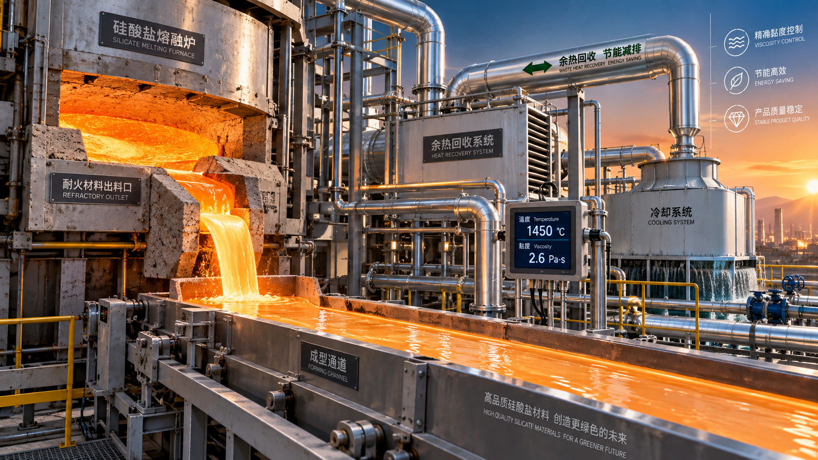
 Optical Glass Tech FellowHow Silicate Industrial Processes Control Viscosity, Energy Use, and Product QualitySilicate industrial processes: learn how viscosity, chemistry, heat transfer, and atmosphere control reduce energy use, improve stability, and protect product quality.Sep 21, 2026
 Thermal Energy ArchitectHow European Plants Can Evaluate Energy Recovery Equipment for High-Temperature ProcessesIndustrial energy recovery equipment Europe: learn how high-temperature plants can assess waste-heat sources, integration risks, lifecycle value, and reliable recovery routes.Sep 20, 2026
 Thermal Energy ArchitectIndustrial Furnace Process Optimization: Reducing Fuel Use Without Sacrificing ThroughputIndustrial process optimization furnace strategies that cut fuel use while protecting throughput. Explore combustion control, heat recovery, refractory performance, and data-driven efficiency gains.Sep 19, 2026
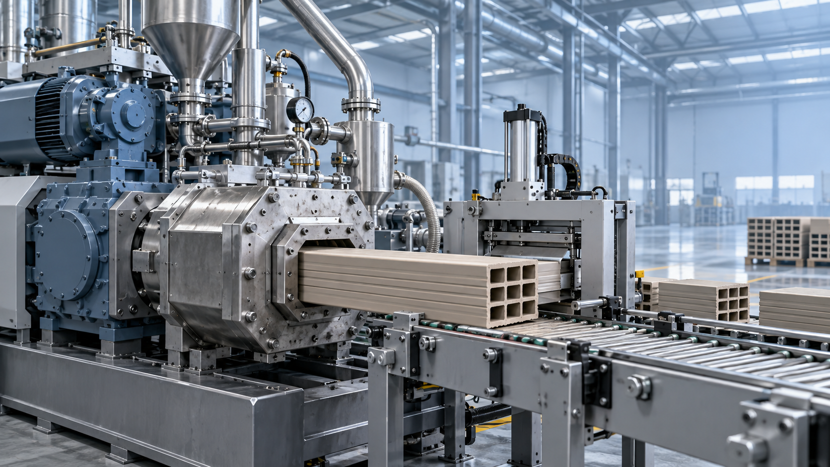
 Ms. Elena RodriguezWhat Drives High-Pressure Extrusion Equipment Cost in Industrial Projects?High pressure extrusion equipment cost explained: compare pressure, die design, automation, wear, energy, and installation factors for smarter industrial investments.Sep 18, 2026
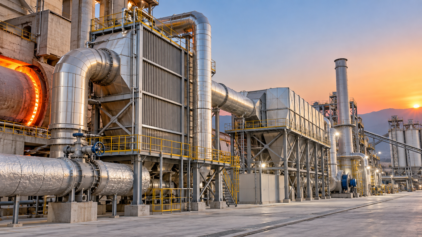
 Thermal Energy ArchitectHow to Size a Waste Heat Recovery Exchanger for High-Temperature Kiln Exhaust?Waste heat recovery exchanger sizing for high-temperature kiln exhaust: balance recoverable duty, fouling, corrosion limits, pressure drop, and reliable heat use.Sep 17, 2026
 Thermal Energy ArchitectWhy Heat-Resistant Materials Lose Abrasion Resistance at High TemperaturesHeat-resistant materials abrasion resistance can decline at high temperatures. Discover the thermal, chemical, and mechanical causes of wear—and how to choose longer-lasting linings.Sep 16, 2026
 Thermal Energy ArchitectHow to Evaluate a Thermal Energy Optimization Company for High-Temperature PlantsChoose a thermal energy optimization company with proven process expertise, measurable savings, and reliable delivery for high-temperature plants. Learn what to assess.Sep 15, 2026
 Thermal Energy ArchitectRotary Kiln Efficiency: How Feed Rate, Fuel Use, and Heat Loss Affect OutputRotary kiln efficiency explained: discover how feed rate, fuel use, heat loss, combustion, and cooling performance shape output, quality, and energy costs.Sep 14, 2026
 Thermal Energy ArchitectHow to Select Heat-Resistant Materials That Maintain Abrasion Resistance in KilnsHeat-resistant materials abrasion resistance: learn how to select kiln linings that withstand heat, wear, thermal cycling, and chemical attack for longer service life.Sep 13, 2026
 Thermal Energy ArchitectHow Rotary Kiln Automation Improves Temperature Control and Fuel EfficiencyRotary kiln technology automation enhances temperature control, stabilizes combustion, and improves fuel efficiency with smarter data, predictive control, and safer operations.Sep 12, 2026
 Silicate Process EngineerCement Plant Emission Control: Selecting Systems for Dust, NOx, and SO2 LimitsCement plant emission control guide: compare dust collectors, NOx reduction, and SO2 systems for reliable compliance across kiln modes, fuel changes, and operating upsets.Sep 11, 2026
 Thermal Energy ArchitectSelecting Abrasion-Resistant High-Temperature Materials for Kiln and Conveyor Wear ZonesHigh-temp material engineering guide to abrasion-resistant kiln and conveyor solutions—match wear, heat, chemistry, and installation design for longer service life.Sep 10, 2026
 Dr. Alistair VaughnIndustrial Process Engineering: How to Map Processes for Safer, More Efficient PlantsIndustrial process engineering reveals bottlenecks, safety risks, and energy losses through practical process mapping for safer, more efficient plants.Sep 09, 2026
 Optical Glass Tech FellowHow to Evaluate a Glass Annealing Equipment Manufacturer for Production StabilityChoose a glass annealing equipment manufacturer with proven thermal uniformity, reliable controls, lifecycle value, and responsive service for stable production.Sep 08, 2026
 Prof. Marcus ChenThermal Energy Architecture in North America: Strategies for Lower Building Energy UseThermal energy architecture North America helps project leaders cut building energy use through stronger envelopes, right-sized HVAC, storage, and smart commissioning.Sep 07, 2026
 Ms. Elena RodriguezHow Should Buyers Evaluate Building Material Industry Intelligence Pricing?Building material industry intelligence pricing: learn how to compare coverage, technical depth, and ROI to choose intelligence that reduces procurement risk.Sep 07, 2026
 Ms. Elena RodriguezHow to Use Building Material Intelligence Data for Market and Investment DecisionsBuilding material industry intelligence data helps leaders evaluate demand, costs, regulation, capacity, and technology to make smarter market and investment decisions.Sep 05, 2026
 Thermal Energy ArchitectHow PLC Control Improves Energy Efficiency and Temperature Stability in KilnsEnergy efficient kilns PLC control improves temperature stability, cuts fuel waste, and optimizes combustion, draft, and material flow. Explore proven strategies for smarter kiln modernization.Sep 04, 2026
 Optical Glass Tech FellowEuropean Glass Melting Processes: Furnace Choices, Energy Use, and Quality ControlGlass melting process Europe: explore furnace choices, energy efficiency, cullet strategy, and quality control to improve output, compliance, and long-term glass performance.Sep 03, 2026
 Thermal Energy ArchitectWhat Determines Refractory Lining Monitoring Price for Industrial Kilns?Refractory lining monitoring price depends on kiln size, sensor technology, installation, software, and support. Compare total lifecycle costs and choose the right solution.Sep 02, 2026





Related News
- 00
0000-00
What Drives High-Pressure Extrusion Equipment Cost in Industrial Projects? - 00
0000-00
How Should Buyers Evaluate Building Material Industry Intelligence Pricing? - 00
0000-00
How to Use Building Material Intelligence Data for Market and Investment Decisions - 00
0000-00
How to Evaluate a Silicate Processing Equipment Manufacturer for Plant Projects - 00
0000-00
Process Equipment Comparison: Which Metrics Matter Most for Reliable Selection?
Weekly Insights
Stay ahead with our curated technology reports delivered every Monday.