
How Glass Furnace Emissions Are Measured and Controlled for Regulatory Compliance




Compliance begins with a defensible answer to a simple question: what is leaving the furnace stack, at what concentration, and under which operating conditions? Glass furnace emissions are not constant. Fuel selection, batch chemistry, cullet ratio, furnace pull, burner balance, oxygen level, raw-material handling, and control-equipment condition can all change the emission profile. A compliant plant therefore needs more than a stack test or a single analyzer reading. It needs a monitoring and control approach that connects measured emissions to real furnace operation.
The pollutants most often considered include particulate matter, nitrogen oxides (NOx), sulfur oxides (SOx), carbon monoxide (CO), carbon dioxide (CO2), acid gases where relevant, and trace substances associated with batch materials or fuel. The exact permit limits, averaging periods, test methods, and reporting obligations depend on the site and jurisdiction. The practical task is to build a measurement system that produces representative, traceable information and a response plan that prevents an abnormal trend from becoming an exceedance.
Start with the emission sources, not the monitoring instrument
A glass furnace exhaust stream is shaped by several sources at once. Fine particulate matter can originate from batch carryover, volatilized alkalis that later condense, and dust released during material handling. NOx is commonly linked to high flame temperatures and nitrogen in combustion air or fuel. SOx depends strongly on sulfur-bearing fuels and batch inputs. CO is an operational signal as well as an air pollutant: elevated CO can indicate incomplete combustion, unstable firing, poor air-fuel mixing, or local reducing conditions.
That distinction matters because the same stack reading can call for very different actions. A rise in particulate loading may point toward batch charging practice, furnace pressure, duct leakage, or baghouse performance. A rise in NOx may be driven by combustion temperature and excess oxygen rather than a failure in particulate control. Treating every excursion as a stack-treatment problem often leads to expensive changes that do not address the source.
Before selecting equipment or setting internal alarms, map each emission to its likely origin, the relevant operating variables, the available abatement system, and the measurement method used for compliance. This turns emission control from an end-of-pipe activity into a controlled production process.
How glass furnace emissions are measured
Most facilities use a combination of continuous monitoring, periodic source testing, and process monitoring. Each method answers a different question. Continuous systems reveal changes over time; periodic testing establishes detailed pollutant measurements and method-based compliance evidence; process data helps explain why the emissions changed.
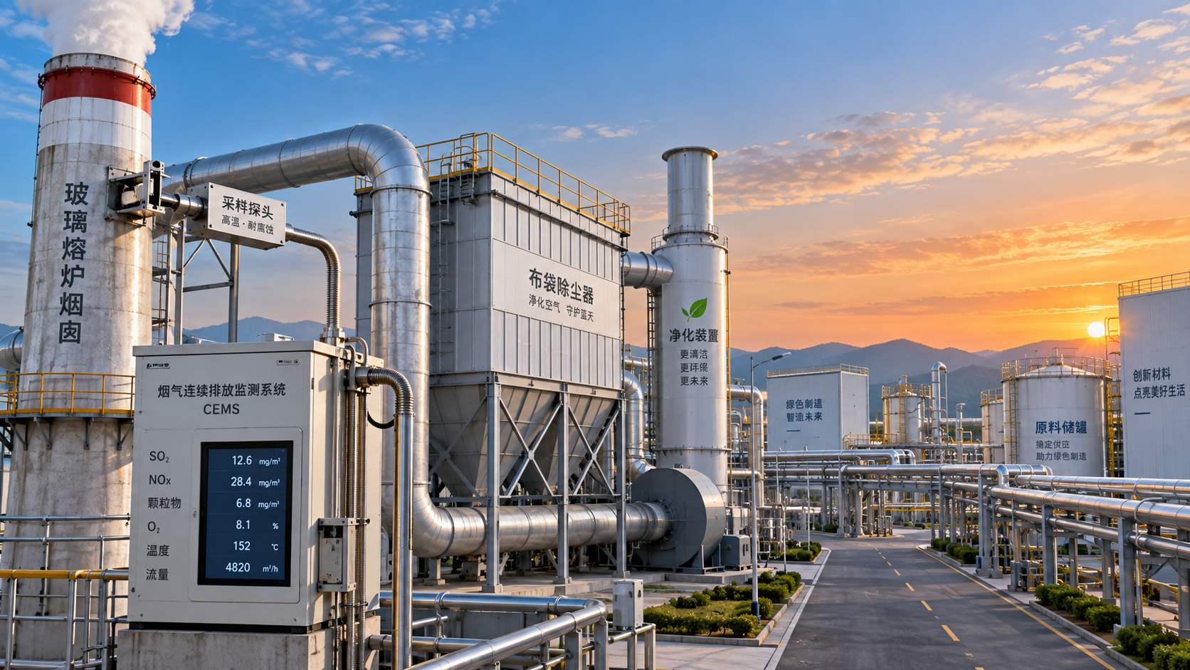
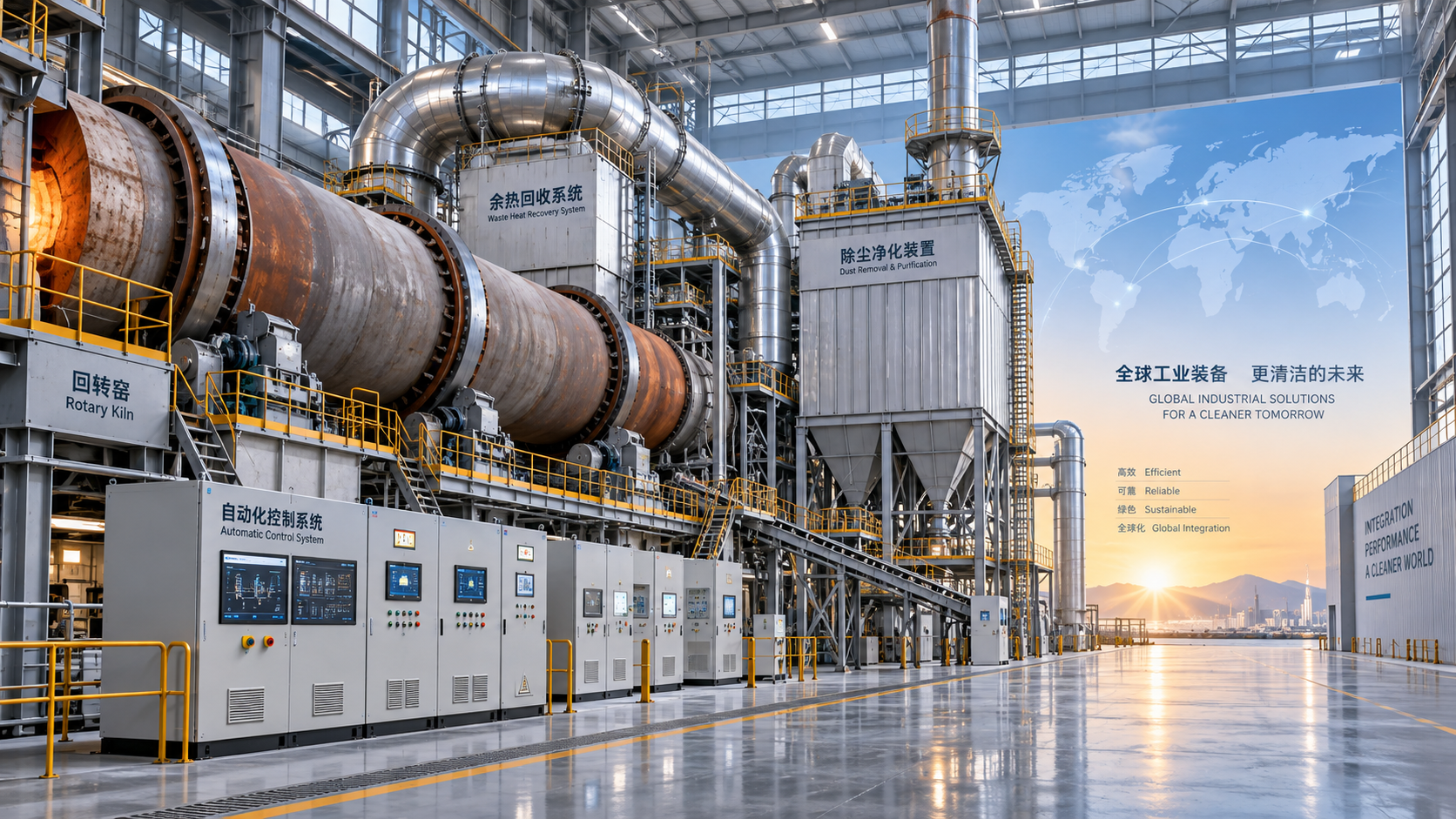
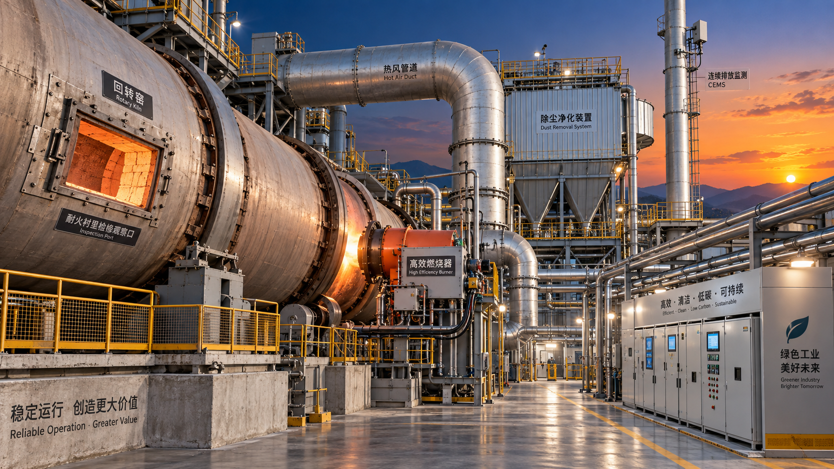
A continuous emissions monitoring system, often called CEMS, generally draws a conditioned sample from the stack or measures directly in the gas path. The system may include a probe, heated sample line, gas conditioning equipment, analyzers, data acquisition hardware, and calibration components. For an extractive system, sample temperature and moisture management are essential. Condensation can remove soluble gas components from the sample or damage the reliability of the measurement. For in-situ measurement, optical path cleanliness, alignment, and the actual stack gas conditions become central concerns.
Oxygen measurement deserves particular attention. Many emissions are reported on a corrected oxygen basis, so an inaccurate oxygen value can distort the reported pollutant concentration even if the pollutant analyzer itself is functioning correctly. Likewise, dry-basis and wet-basis results are not interchangeable. The reporting basis, reference oxygen condition, averaging convention, and units should be established before data is compared with a permit limit.
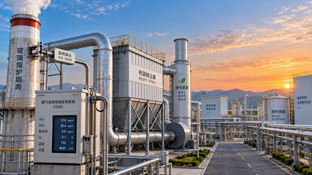
Particulate measurement is more nuanced than it first appears. A continuous particulate monitor can provide valuable real-time indication of changes after an electrostatic precipitator, baghouse, or other control device. However, its output may be based on an optical, triboelectric, or other relative signal. Its relationship to mass concentration must be managed through the applicable calibration and quality-assurance approach. A stable-looking monitor is not proof that the measurement remains representative after ductwork changes, altered dust properties, instrument maintenance, or process modifications.
Representative operation is part of a valid measurement
Emission numbers only have compliance value when the operating record explains the conditions behind them. During a stack test or a performance demonstration, record furnace pull, fuel mix, batch composition, cullet percentage, combustion settings, bypass status, control-device operating parameters, and any upset condition. A test run at reduced pull or unusually clean raw-material conditions may not reflect normal production. Conversely, a temporary upset should be identified rather than silently allowed to define the unit’s expected performance.
Routine data should be reviewed in the same way. A daily average can hide short, meaningful excursions. Short-duration peaks may reveal charging events, burner instability, cleaning cycles, reagent interruptions, or filter problems that deserve investigation even when the longer average remains below the applicable limit.
Data quality is a compliance control, not an administrative task
Calibration, zero and span checks, preventive maintenance, validation rules, and data substitution procedures are frequently treated as separate environmental paperwork. In practice, they determine whether an emissions record can withstand scrutiny and whether operators can rely on it during an upset.
For a continuous system, establish clear ownership for routine checks and alarms. Analyzer drift, sample-line blockage, failed heaters, degraded filters, loss of instrument air, and communication faults should have defined actions. An analyzer that reports a plausible but biased value is more dangerous than an obvious failure because it can delay corrective action.
It is also important to distinguish between a process event and a monitoring event. If NOx rises while furnace temperature, oxygen, and firing demand change in a consistent pattern, the emission increase may be operational. If the pollutant signal jumps but supporting variables remain unchanged, inspect the measurement system before changing burners or reagent rates. Both possibilities require timely review, but they should not be treated as identical.
Good records link the following information in one reviewable trail:
- Raw and corrected pollutant readings, including the reporting basis used for compliance.
- Calibration and maintenance activity, analyzer status, and periods of invalid data.
- Furnace operating conditions that can influence emissions.
- Control-device parameters such as pressure drop, electrical settings, temperature, reagent feed, and cleaning status.
- Alarm events, investigation findings, corrective actions, and confirmation that the response worked.
This linkage is especially useful when a regulator, internal auditor, or plant leadership asks why a result changed. A chart showing only concentration provides a symptom. A synchronized record of emissions, furnace conditions, and abatement performance provides an explanation.
Matching control methods to the pollutant
There is no single glass furnace emission-control system that performs equally well for every pollutant. Control selection should begin with the emission source, expected operating range, gas temperature, dust characteristics, available space, maintenance capability, and interactions with product quality and furnace life.
Particulate matter is commonly controlled with equipment designed to capture entrained and condensed dust, such as electrostatic precipitators or fabric filters. The practical difference is not simply capture efficiency. Temperature tolerance, dust resistivity, gas conditioning, pressure drop, cleaning requirements, bag material selection, and sensitivity to moisture or sticky alkali-rich dust can determine whether the system remains stable over time. A device that performs well on paper may be unsuitable if the gas stream causes rapid blinding, corrosion, or deposits.
NOx control usually combines combustion discipline with, where needed, downstream reduction. Low-NOx firing strategies can reduce formation at the source, but they must be evaluated against flame shape, heat transfer, glass quality, furnace pressure, and fuel flexibility. Selective reduction systems can provide additional control, yet their performance depends on temperature window, reagent distribution, mixing, catalyst condition where used, and the risk of reagent slip. Installing reduction equipment without stabilizing combustion often produces variable results and harder troubleshooting.
SOx and acid-gas control may require attention to fuel sulfur, batch chemistry, and dry or wet scrubbing approaches. The appropriate route depends on the gas composition and the management of collected or reacted material. A change in raw material can affect not only stack emissions but also the waste stream from the control system. That downstream consequence should be assessed before a chemistry-based control strategy is adopted.
CO is typically best treated as a combustion-control indicator. Raising excess air can reduce CO in some cases, but excessive air can increase fuel use, alter furnace thermal conditions, and affect NOx formation. The correct response is usually to examine burner performance, air-fuel ratio control, mixing, firing pattern, pressure balance, and maintenance condition rather than applying a single blanket adjustment.
CO2 is different from conventional pollutants because it is primarily tied to fuel combustion and carbonate decomposition in the batch. Continuous measurement may support greenhouse-gas accounting and energy analysis, while actual reduction depends on broader choices: furnace efficiency, heat recovery, fuel transition, cullet use, batch formulation, production scheduling, and furnace design. A carbon monitor is useful, but it does not by itself reduce carbon intensity.
Control-system alarms should lead to defined decisions
An alarm that only tells someone to “check emissions” is rarely enough. Internal action thresholds should be arranged to provide time for diagnosis before a compliance limit is approached. The thresholds should account for normal process variation, analyzer response time, averaging requirements, and the time needed to make a meaningful correction.
A practical response sequence is:
- Confirm that the reading is valid by checking analyzer status, calibration condition, sample flow, temperatures, and supporting measurements.
- Identify whether the deviation aligns with a known furnace or control-device change, such as charging, fuel switching, pressure fluctuation, or cleaning activity.
- Check the relevant control parameters before making broad furnace adjustments.
- Apply the approved operating response and document the action, timing, and observed result.
- Escalate recurring deviations into a root-cause review rather than accepting repeated manual correction as normal operation.
The fifth step is often where improvement is lost. Repeated adjustment of reagent feed, burner settings, or cleaning cycles can keep a plant within limits while concealing a deteriorating probe, a leaking duct, a worn valve, a changing batch material, or declining control-device condition. Trends matter more than isolated alarms.
Common compliance mistakes in glass furnace emissions management
One frequent mistake is choosing a monitor based only on the pollutant list. Installation location, gas temperature, particulate loading, access for maintenance, sample transport distance, and the reliability of utilities can have just as much impact on usable data. A sophisticated analyzer installed at a poor sampling point will not solve a representativeness problem.
Another is separating environmental monitoring from furnace control. Stack data should be available alongside furnace and abatement data in a form that supports rapid diagnosis. The Global Cera-Forge Hub (CF-Elite) tracks developments in glass production monitoring and thermal-process intelligence, reflecting a useful operating principle: emissions performance becomes easier to manage when high-temperature process behavior, control-equipment condition, and environmental data are interpreted together.
A third mistake is assuming that a compliance test is the finish line. A passing test confirms performance under documented conditions; it does not guarantee stable performance after changes in fuel, batch, furnace campaign condition, production rate, or maintenance practice. Any material or operating change that could alter the exhaust stream should trigger a review of monitoring range, alarm settings, abatement capacity, and recordkeeping needs.
What to confirm before changing a monitoring or abatement system
Begin with the actual compliance obligation and its reporting basis. Then compare it with the current emissions profile, not only average results but also peak behavior and recurring events. Review the stack configuration, gas characteristics, existing controls, maintenance access, available utilities, and the plant’s ability to operate and maintain the proposed system.
The most effective solution is usually the one that makes the emissions record more reliable while reducing the need for emergency intervention. That may mean improving combustion control before adding NOx treatment, repairing pressure and dust-control problems before replacing a particulate monitor, or integrating emissions and process trends before setting tighter alarms. For glass furnace compliance, measurement and control are one operating discipline: the data must be trustworthy enough to guide the action, and the action must be specific enough to change the result.
Related News
 Optical Glass Tech FellowHow Glass Furnace Emissions Are Measured and Controlled for Regulatory ComplianceGlass furnace emissions: learn how to measure, monitor, and control NOx, SOx, particulate, CO, and CO2 for reliable regulatory compliance.Oct 08, 2026
 Prof. Marcus ChenIndustrial Decarbonization Strategies in Europe: A Roadmap for Energy-Intensive PlantsIndustrial decarbonization strategies Europe: explore practical pathways for energy-intensive plants to cut emissions, improve efficiency, and protect performance.Oct 07, 2026
 Thermal Energy ArchitectEnergy-Efficient Silicate Production Lines: What to Compare Before SelectionSilicate production lines energy efficient selection guide: compare thermal performance, stability, emissions, controls, and lifecycle value before investing.Oct 06, 2026
 Optical Glass Tech FellowHow to Evaluate Automated Float Glass Lines for Capacity, Quality, and Energy UseEvaluate automated float glass lines for net capacity, consistent quality, energy efficiency, automation reliability, and lifecycle value. Explore key criteria for smarter investment decisions.Oct 05, 2026
 Thermal Energy ArchitectWhat Does CE Marking Require for an Energy-Efficient Industrial Kiln?Energy efficient kiln CE requirements explained: assess safety, technical files, energy performance, and EU compliance before purchase or commissioning.Oct 04, 2026
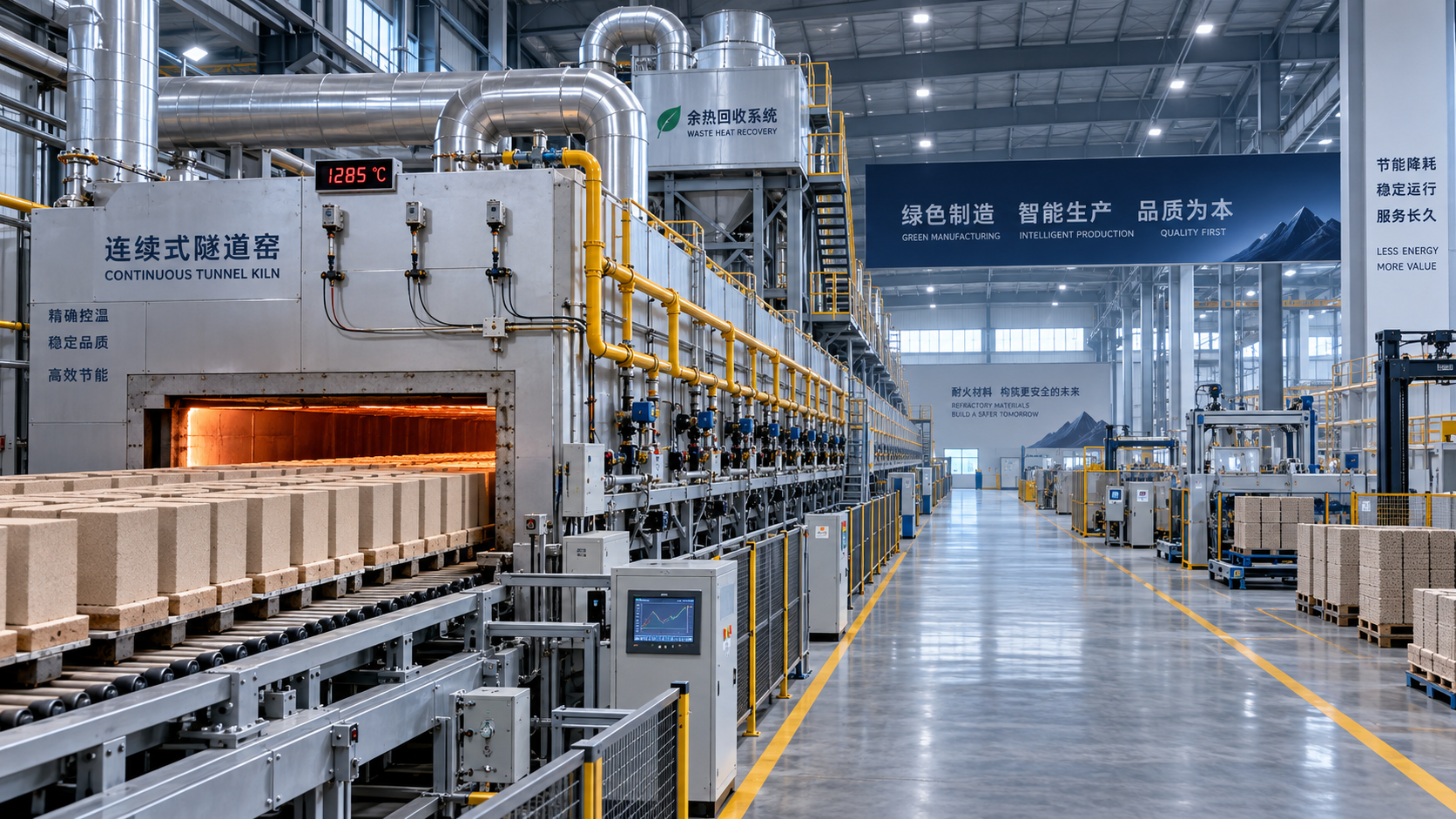
 Thermal Energy ArchitectRefractory Manufacturing Solutions for Brick Plants: How to Extend Kiln LifeRefractory manufacturing solutions for brick plant operations: discover proven strategies to extend kiln life, reduce heat loss, prevent lining failures, and plan cost-effective repairs.Oct 03, 2026
 Thermal Energy ArchitectHow to Specify Heavy Industrial Process Systems for High-Temperature PlantsHeavy industrial processes systems: learn how to specify high-temperature plants for efficiency, emissions control, maintainability, and lifecycle performance.Oct 02, 2026
 Structural Material AnalystHow Sustainable Material Extrusion Can Improve Wall Panel Durability and Design FlexibilityDiscover how sustainable material extrusion for wall panels improves durability, moisture resistance, design flexibility, and installation consistency for high-performing wall systems.Oct 01, 2026
 Thermal Energy ArchitectHow to Evaluate a High-Temperature Materials Manufacturer for Furnace ApplicationsChoose a high-temperature materials manufacturer with confidence: compare thermal performance, chemical resistance, quality controls, installation support, and lifecycle cost.Sep 30, 2026
 Ms. Elena RodriguezHow to Structure Global Specification Data for Faster Industrial Product EvaluationGlobal specification-oriented product information helps industrial teams compare capacity, energy, emissions, automation, and lifecycle data on a like-for-like basis for faster, confident equipment decisions.Sep 29, 2026
 Thermal Energy ArchitectHow to Specify High-Temperature Process Systems for Continuous Thermal OperationsHigh-temperature process engineering systems: learn how to specify resilient continuous thermal operations for efficiency, compliance, reliable uptime, and long-term performance.Sep 28, 2026
 Thermal Energy ArchitectHow to Evaluate a Thermal Engineering Contractor for High-Temperature Plant ProjectsChoose a thermal engineering contractor with proven process expertise, lifecycle value, emissions control, and delivery discipline for reliable high-temperature plant performance.Sep 27, 2026
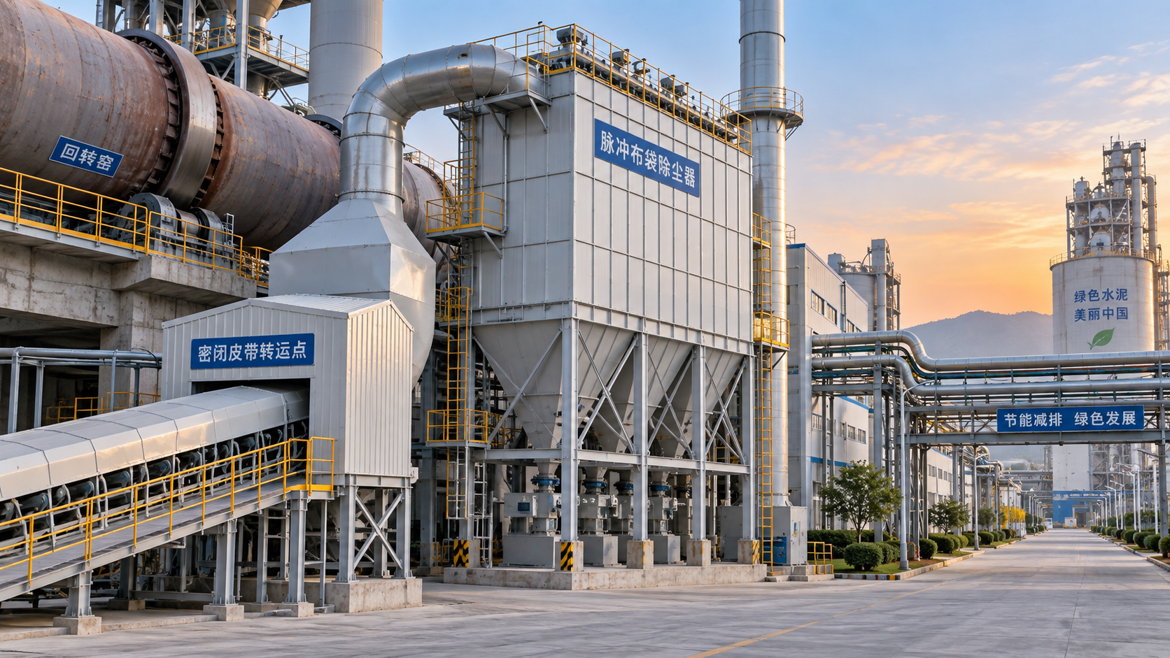
 Silicate Process EngineerHow Latin American Cement Plants Can Reduce Dust Emissions in Kilns and Transfer PointsCement plant dust control Latin America: reduce kiln and transfer-point emissions with practical airflow, filtration, monitoring, and maintenance strategies.Sep 26, 2026
 Material Heat-Resist ExpertHow to Evaluate Refractory Production Lines for Output, Quality, and Energy UseRefractory production lines: learn how to assess qualified output, consistent quality, and total energy use for smarter, lower-risk investment decisions.Sep 25, 2026
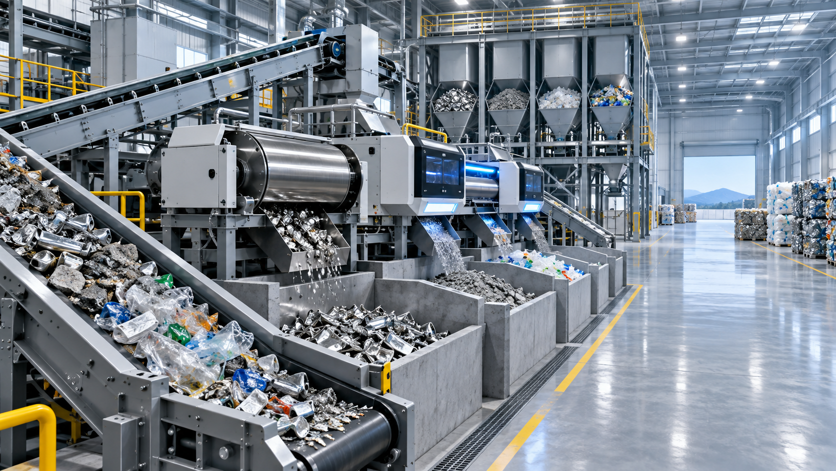
 Dr. Alistair VaughnHow Waste Recycling Technology Improves Material Recovery in Industrial PlantsWaste recycling technology improves material recovery through source segregation, smart separation, thermal treatment, and quality control for industrial plants.Sep 24, 2026
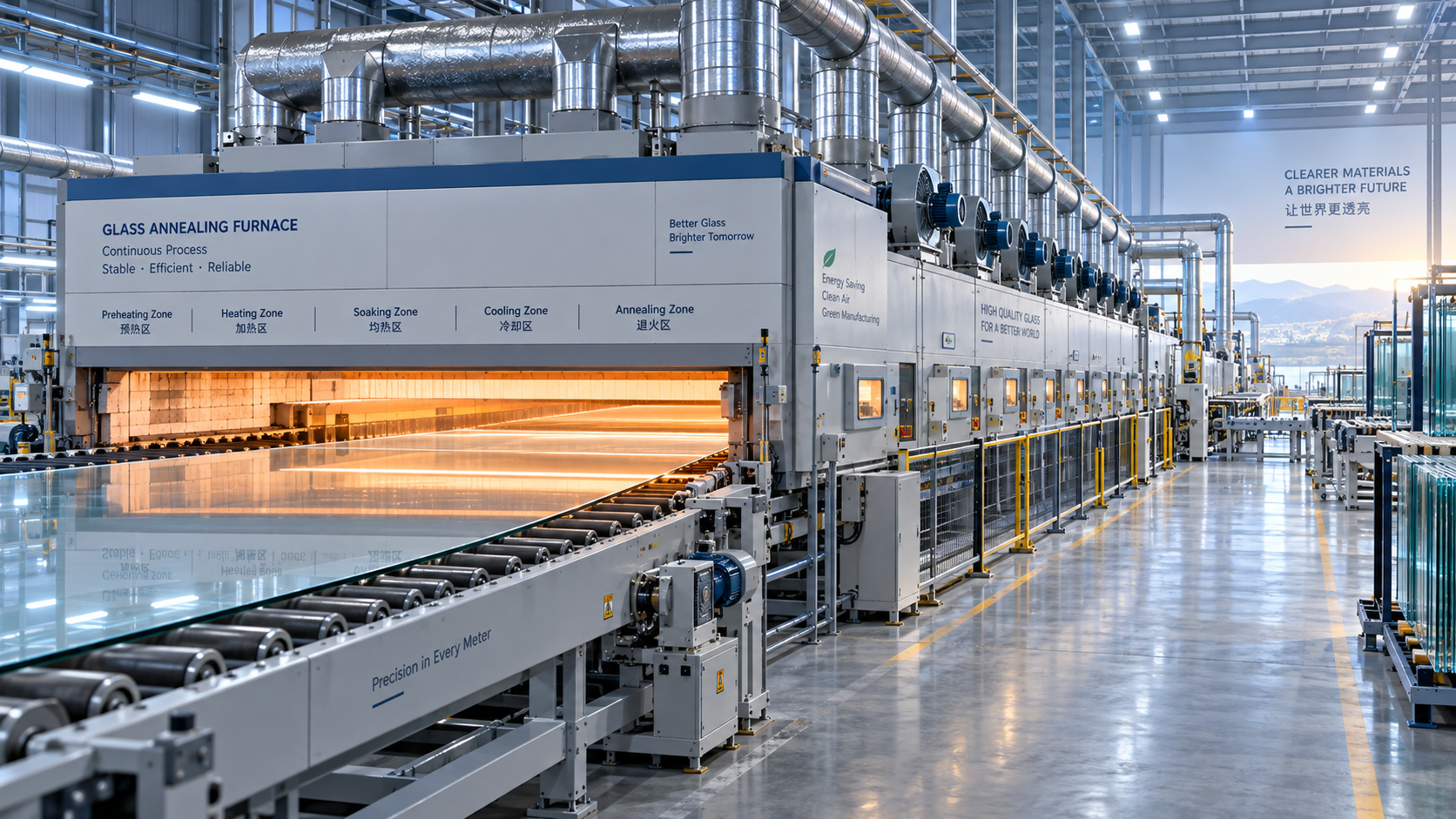
 Optical Glass Tech FellowHow to Specify Glass Annealing Equipment for European Quality and Energy RequirementsGlass annealing equipment Europe: learn how to specify lehrs for consistent glass quality, energy efficiency, compliance, automation, and reliable long-term performance.Sep 23, 2026
 Optical Glass Tech FellowSilicate Process Automation: Improving Batch Consistency and Energy ControlSilicate process automation improves batch consistency, energy control, traceability, and operator confidence across high-temperature manufacturing operations.Sep 22, 2026
 Optical Glass Tech FellowHow Silicate Industrial Processes Control Viscosity, Energy Use, and Product QualitySilicate industrial processes: learn how viscosity, chemistry, heat transfer, and atmosphere control reduce energy use, improve stability, and protect product quality.Sep 21, 2026
 Thermal Energy ArchitectHow European Plants Can Evaluate Energy Recovery Equipment for High-Temperature ProcessesIndustrial energy recovery equipment Europe: learn how high-temperature plants can assess waste-heat sources, integration risks, lifecycle value, and reliable recovery routes.Sep 20, 2026
 Thermal Energy ArchitectIndustrial Furnace Process Optimization: Reducing Fuel Use Without Sacrificing ThroughputIndustrial process optimization furnace strategies that cut fuel use while protecting throughput. Explore combustion control, heat recovery, refractory performance, and data-driven efficiency gains.Sep 19, 2026

Related News
- 00
0000-00
How Glass Furnace Emissions Are Measured and Controlled for Regulatory Compliance - 00
0000-00
How to Evaluate Automated Float Glass Lines for Capacity, Quality, and Energy Use - 00
0000-00
How to Specify Glass Annealing Equipment for European Quality and Energy Requirements - 00
0000-00
Silicate Process Automation: Improving Batch Consistency and Energy Control - 00
0000-00
How Silicate Industrial Processes Control Viscosity, Energy Use, and Product Quality
Weekly Insights
Stay ahead with our curated technology reports delivered every Monday.